Electronic unit of textile machine for producing across winding reel

A technology for cross-winding bobbins and electronic units, which is applied in the direction of continuous winding spinning machines, spinning machines, textiles and paper making, etc., to achieve the effect of reducing quantity, saving extra expenses, and reducing laying costs

Active Publication Date: 2012-03-14
ZHUOLANG INTELLIGENT MACHINERY CO LTD
View PDF2 Cites 0 Cited by
  • Summary
  • Abstract
  • Description
  • Claims
  • Application Information

AI Technical Summary

Problems solved by technology

Optionally, the entire control unit must also be replaced

Method used


Image

  • Electronic unit of textile machine for producing across winding reel
  • Electronic unit of textile machine for producing across winding reel
  • Electronic unit of textile machine for producing across winding reel

Examples


Embodiment Construction

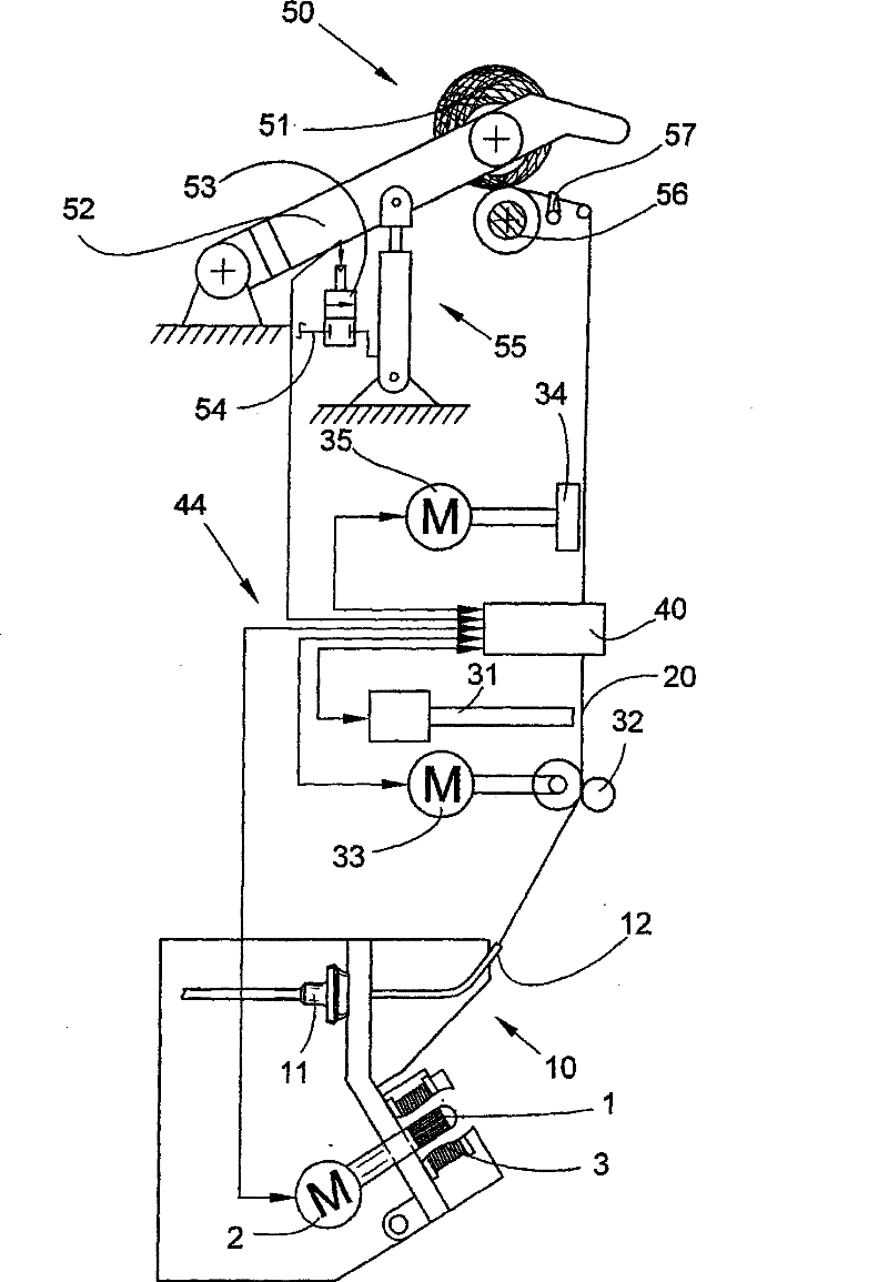
[0026] figure 1 A schematic diagram showing a rotor spinning machine according to the invention. A fiber tow (not shown here) is conveyed by a tow feed drum 1 to a tow opening roller 3 . In this case, the tow feed drum 1 is driven by a feed motor 2 . The opened fiber bundle is fed to a spinning pot 10 with a spinning cup 11 . In the illustrated embodiment, the spinning cups are driven centrally via belt (not shown) transmission, in other words, the spinning cups of several workstations are driven simultaneously via a central drive. Optionally, however, a single electric drive can also be used for the spinning rotor.

[0027] The yarn 20 is drawn out of the spinning pot 10 by the yarn drawing nozzle 12 and forwardly delivered to the winding device 50 by the yarn drawing device 32 driven by the drawing motor 33 . The suction device 31 used in the splicing process is also arranged above the yarn drawing device 32 . Before the yarn 20 is wound onto the cross-wound bobbin 51, ...


PUM


Abstract

This invention refers to an electronic unit of spinner for producing cross-winding bobbin. The spinner includes numerous similar workstations, each of which comprises an independent controller. The controller is integrated to electronic units (40, 60) having operation components (42, 63) and display components (43, 64) and actuates at least one executor (2, 33, 31, 35, 53) in the workstations, wherein the electronic unit is integrated with a yarn sensor. And the independent controller estimates a measuring signal of the yarn sensor and actuates at least one executor in the workstations according to the measuring signal.

Description

technical field [0001] The invention relates to a textile machine for the production of cross-wound bobbins having a large number of similar workstations, each of which has an independent control device integrated into an electronic unit with operating and display elements and actuating the At least one actuator. Background technique [0002] EP 1065303 discloses a conventional textile machine. The arrangement of the operating and display elements on the individual workstations, as described in this document, is particularly advantageous, since the displayed data can be directly related to the individual workstations without risk of confusion. This is especially relevant if the operator has to or wants to intervene on the basis of the displayed data. The operator can confirm interventions at the workstation by operating elements or triggering control functions. A particularly space-saving and simple arrangement is obtained by integrating the control device and the operati...

Claims


Application Information

Patent Timeline
Patent Type & Authority Patents(China)
IPC IPC(8): D01H13/26D01H13/14D01H1/16B65H54/22B65H63/00
CPCD01H4/42D01H4/44B65H2701/31D01H13/14B65H63/02B65H63/062B65H63/036B65H2402/10
Inventor 卡尔・坎普斯拉尔夫・西韦特克里斯托夫・哈泽
Owner ZHUOLANG INTELLIGENT MACHINERY CO LTD
Why Eureka
Try Eureka