Electronically commutated direct current machine sensor-less operation

A DC motor and electronic commutation technology, which is applied in the direction of electronic commutator, electronic commutation motor control, electrical components, etc., can solve the problems of inapplicability and cannot be used to determine the rotor position, and achieve the effect of reducing the number

Active Publication Date: 2009-02-25
SAURER GERMANY GMBH & CO KG
View PDF0 Cites 6 Cited by
  • Summary
  • Abstract
  • Description
  • Claims
  • Application Information

AI Technical Summary

Problems solved by technology

The problem here is that due to the demagnetization process and due to disturbances such as electrostatic discharges, the resulting zero crossings are not relevant zero crossings for this induced voltage, since they are not induced in the stator windings by the rotating field of the rotor, so Also cannot be used to determine rotor position
[0005] This approach is completely unsuitable for rotational speeds significantly greater than 100,000 revolutions per minute, such as occur in rotor drives of open-end spinning machines

Method used


Image

  • Electronically commutated direct current machine sensor-less operation
  • Electronically commutated direct current machine sensor-less operation
  • Electronically commutated direct current machine sensor-less operation

Examples


Embodiment Construction

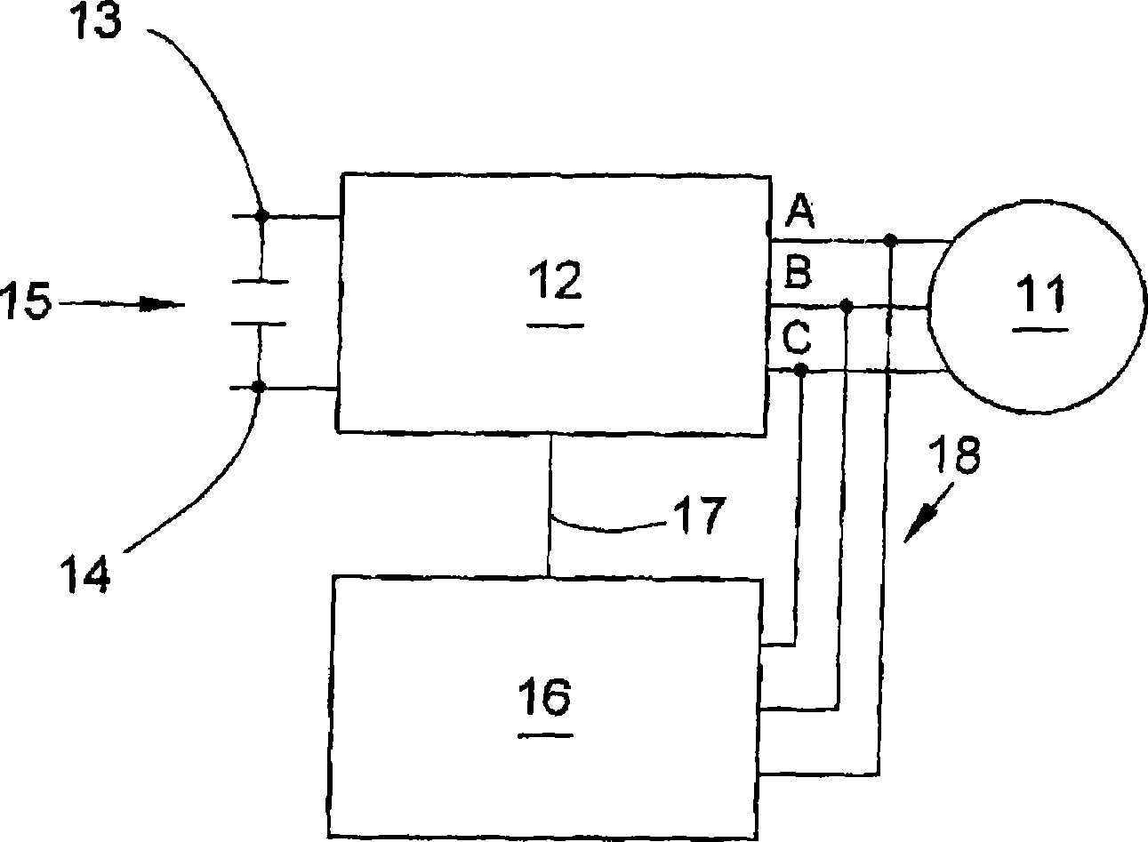
[0040] figure 1 A schematic diagram of an electronic drive according to the invention with an electronically commutated DC motor 11 is shown. The motor 11 consists of three-phase current windings in the stator and a permanent magnet excitation rotor. The terminals of the three phases A, B and C are connected to the inverter 12 . The inverter is connected to a DC voltage source. DC voltage source at figure 1 is represented by capacitor 15 and is connected to terminals 13 and 14 of the inverter. The inverter is controlled by a control unit 16 , and the inverter and the control unit are connected to each other by a control line 17 . The measurement line 18 connects the control device 16 to the three phases A, B and C to measure the induced voltage.

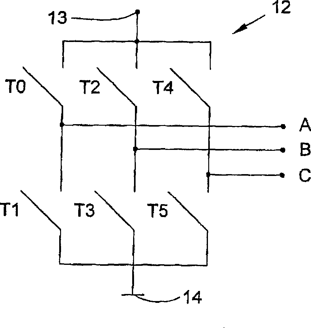
[0041] figure 2 The basic structure of an inverter 12 with DC voltage connections 13 and 14 and phase connections A, B and C is shown. The inverter is a three-phase bridge circuit with switches T0 to T5. The switch is config...


PUM


Abstract

The invention relates to an operation method of non-sensor of electronic inverting direct-current motor (11) and an electronic driver with the motor (11), an inverter (12) and a control device (16), comprising: confirming zero crossing point of the voltage induced by the rotation field of rotor in phases without supply current; detecting presence of the zero crossing point; calculating moment of the next zero crossing point of voltage induced by the rotation field of the rotor in advance; and at least evaluating the finally detected zero crossing point in the time interval (delta) after the moment calculated in advance.

Description

technical field [0001] The invention relates to a method for sensorless operation of an electronically commutated direct current motor, wherein the zero crossing of the voltage induced by the rotating field of the rotor in phases not supplied with current is determined, and to a method with electronically commutated Electronic drives to DC motors, inverters and controls configured for sensorless operation of the motor and for determining the zero crossings of the voltage induced by the rotating field of the rotor in phases where no current is supplied. Background technique [0002] Electronically commutated DC motors are gradually replacing traditional DC motors with mechanical commutators and are used as drives in the automotive sector, household appliances, and industrial applications. Electronically commutated DC motors are concerned with the construction of permanent magnet excited synchronous machines associated with an inverter controlled by a controller or processor t...

Claims


Application Information

Patent Timeline
Patent Type & Authority Applications(China)
IPC IPC(8): H02P6/18
CPCH02P6/182
Inventor 努尔-埃丁·巴勒布勒斯文·梅尔坎普
Owner SAURER GERMANY GMBH & CO KG
Why Eureka
Try Eureka