Hydraulic mechanism for vehicle

A hydraulic mechanism and hydraulic technology, applied in the direction of hydraulic brake transmission, mechanical equipment, non-mechanical drive clutch, etc., can solve the problem of occupying vehicle space, achieve the effect of improving precision, realizing miniaturization, and improving carrying capacity

Inactive Publication Date: 2009-03-04
HONDA MOTOR CO LTD
View PDF1 Cites 11 Cited by
  • Summary
  • Abstract
  • Description
  • Claims
  • Application Information

AI Technical Summary

Problems solved by technology

[0012] In addition, since the front wheel master cylinder 13 and the front wheel slave cylinder 17 are separated by the distance between the connecting ar

Method used


Image

  • Hydraulic mechanism for vehicle
  • Hydraulic mechanism for vehicle
  • Hydraulic mechanism for vehicle

Examples


Embodiment Construction

[0064] The best mode for carrying out the present invention will be described below with reference to the drawings. In addition, look at the picture according to the direction of the symbol.

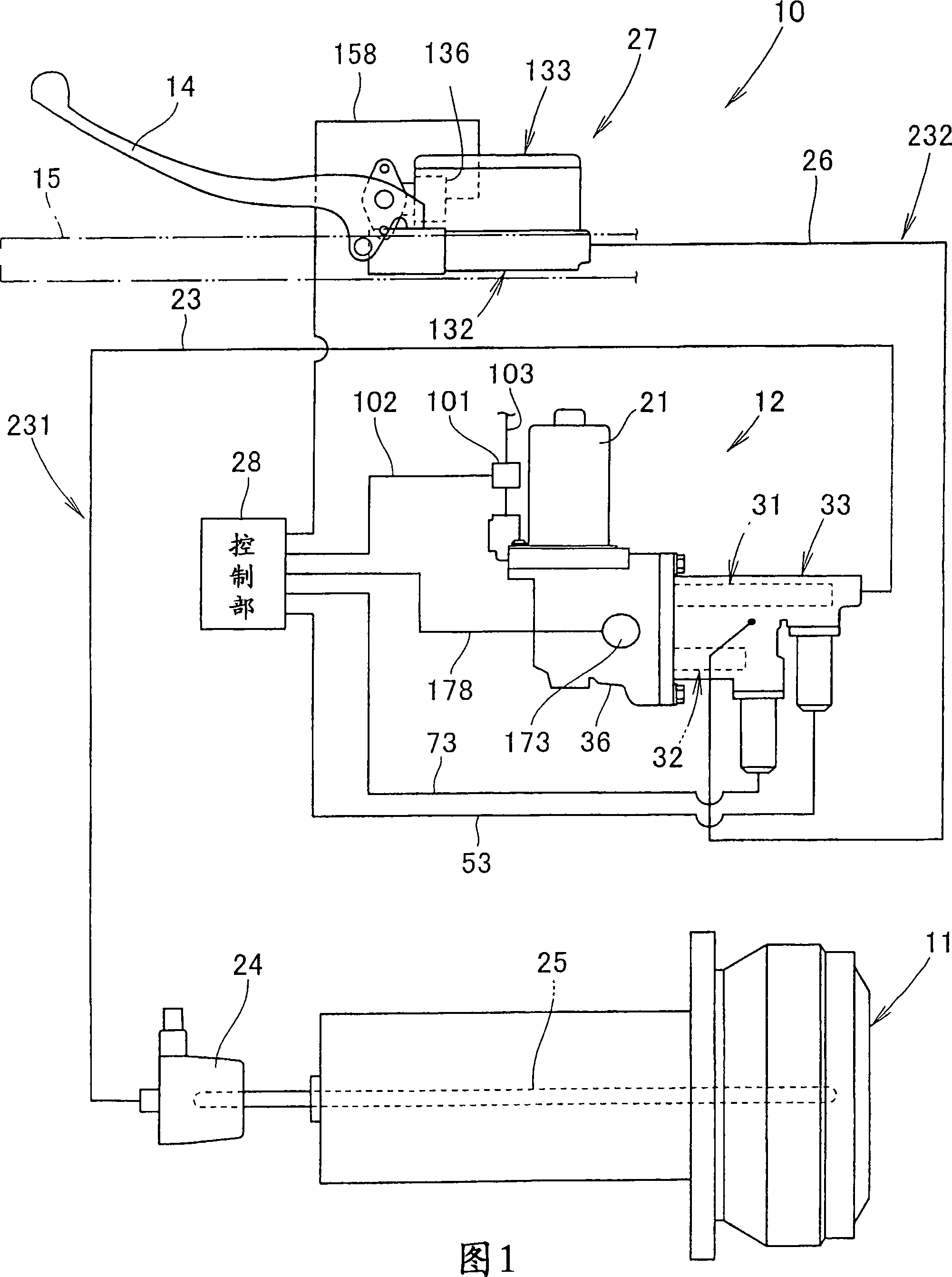
[0065] 1 is a system diagram showing a clutch hydraulic mechanism for a vehicle according to the present invention. When a clutch hydraulic mechanism 10 utilizes a clutch 11 to transmit and disconnect power between an engine and a transmission of a saddle-type vehicle such as a motorcycle or an off-road vehicle, Usually detect the stepping force and vehicle speed of the gear shifting pedal. In the case of gear shifting, for example, the clutch 11 can be automatically disconnected (that is, disconnected or connected) by the actuator unit 12, and the clutch 11 can be manually disconnected or connected by the clutch lever 14 as required.

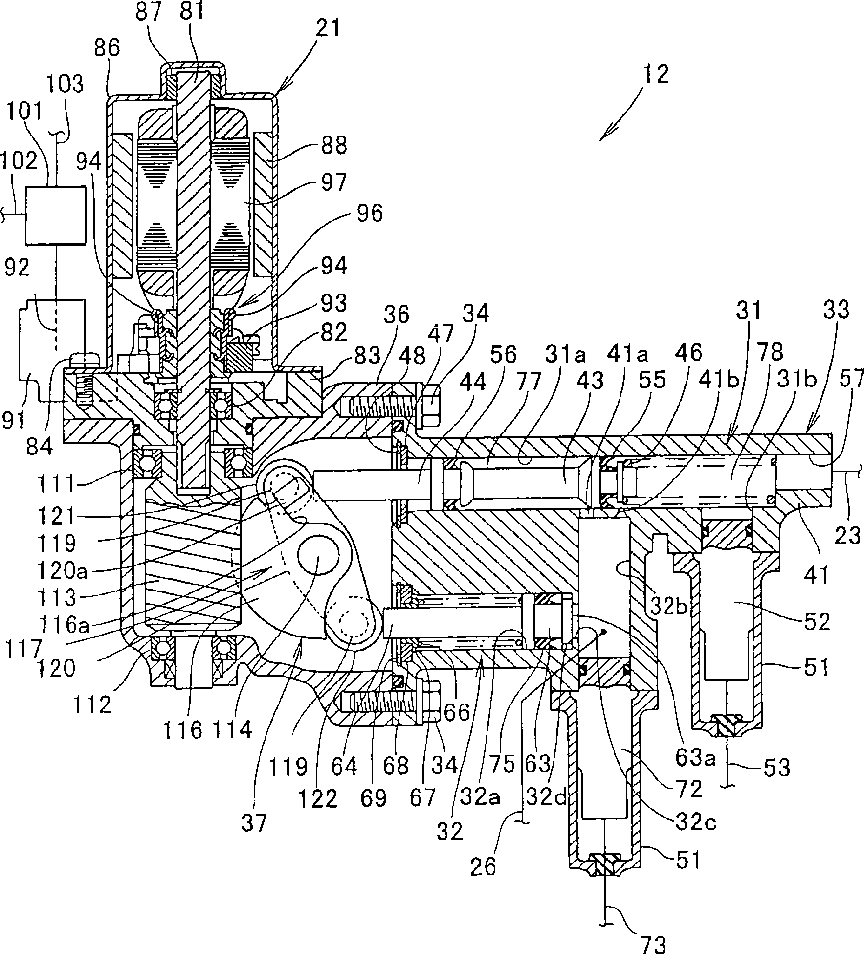
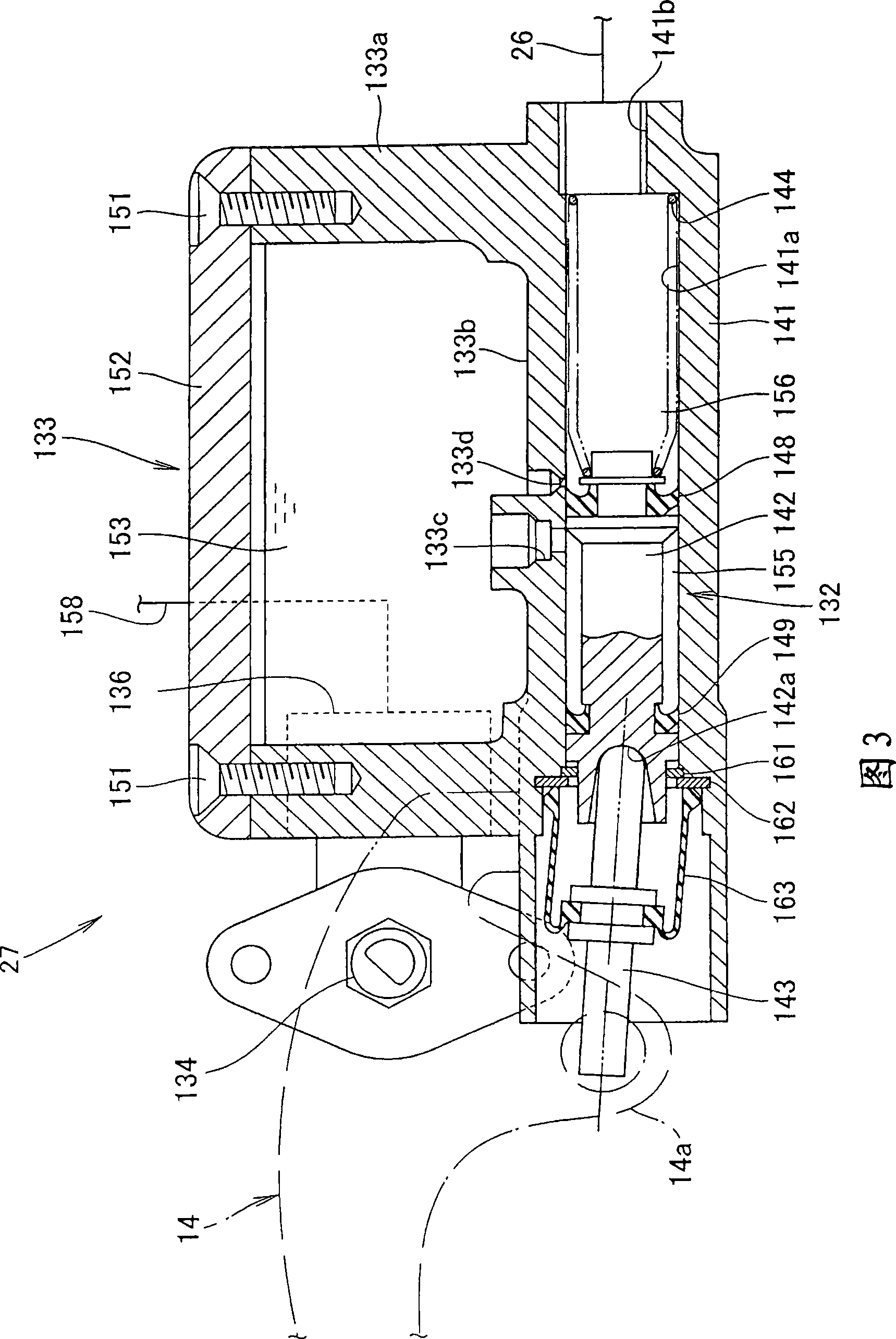
[0066] The clutch hydraulic mechanism 10 includes an actuator unit 12, a first release cylinder 24, a push rod 25, a rod operating portion 27, and a cont...


PUM


Abstract

The invention provides a clutch hydraulic mechanism capable of realizing miniaturization with no change in the position relationship of two hydraulic cylinders. A lever member (117) for transmitting motive power is provided between a second release cylinder (32) and a first master cylinder (31), while the first master cylinder (31) and the second release cylinder (32) are formed in the same cylinder block (41). This eliminates the need for adjusting the positions of the first master cylinder (31) and the second release cylinder (32). Besides, it is possible to dispose the first master cylinder (31) and the second release cylinder (32) close to each other.

Description

technical field [0001] The present invention relates to improvements in hydraulic systems of vehicles. Background technique [0002] As is well known, a conventional vehicle hydraulic mechanism operates one hydraulic piston with two operating forces (for example, refer to Patent Document 1). [0003] Patent Document 1: Japanese Unexamined Patent Publication No. 9-254771 [0004] FIG. 1 and FIG. 4 of Patent Document 1 will be described as follows. [0005] The front wheel brake operating lever 11 is supported freely swingably on the support shaft 77 together with the arc-shaped interlocking part 76, and one end of the interlocking part 76 is in contact with the end of the piston rod 58, which is connected to the front wheel. The master piston 57 of the master cylinder 13 is provided integrally, and the other end of the interlocking member 76 is in contact with the end of the piston rod 70 provided integrally with the piston 69 of the front wheel slave cylinder 17 . [0006...

Claims


Application Information

Patent Timeline
IPC IPC(8): B60T11/24
CPCF16D29/005F16D2048/0254F16D48/02
Inventor 早川公视岩下调家田义久佐保田克三友田明彦
Owner HONDA MOTOR CO LTD
Why Eureka
Try Eureka