
Transmission with gear wheel pump

A technology for transmissions and gear pumps, applied in gear lubrication/cooling, belts/chains/gears, pumps, etc., can solve problems such as increased cost and leaks, reduce slap noise, promote passive lubrication, and benefit The effect of conveying capacity and working reliability

Inactive Publication Date: 2009-03-04
GM GLOBAL TECH OPERATIONS LLC
View PDF1 Cites 5 Cited by
  • Summary
  • Abstract
  • Description
  • Claims
  • Application Information

AI Technical Summary

Problems solved by technology

However, in this solution, the cover must be fixedly connected and sealed to the transmission housing, which increases the cost and also faces the risk that it may not be sealed

Method used


Image

  • Transmission with gear wheel pump
  • Transmission with gear wheel pump

Examples


Embodiment Construction

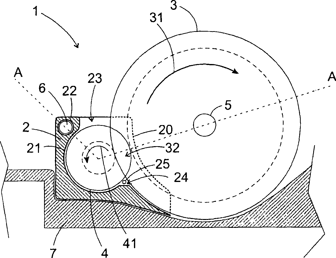
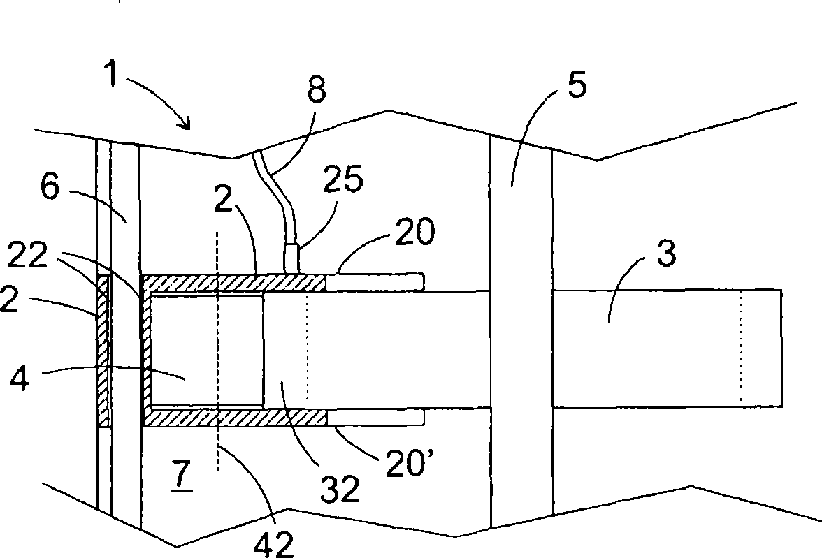
[0024] figure 1 A part of a vehicle transmission is shown, in particular a partial sectional view of a transmission with an external gear pump according to the invention is schematically shown.

[0025] The transmission includes a drive shaft, an output shaft and a plurality of gear sets, the gear sets engage the drive shaft and the output shaft with different transmission ratios and are arranged inside the transmission housing 7 . Furthermore, the transmission includes a gear pump 1 which is likewise surrounded by a transmission housing 7 .

[0026] The gear pump 1 is designed as an external gear pump and has a housing 2, a first gear 3 and a second gear 4, wherein the housing 2 and the second gear 4 are made of a plastic.

[0027] The first gear 3 is formed by a transmission gear in a gear set of the transmission, so the gear set and the gear pump 1 have a common gear 3 . The gear 3 is fixedly arranged on the transmission shaft 5 , is driven by it, and rotates about the ax...


PUM


Abstract

The invention relates to a gearbox for a motor vehicle that includes, but is not limited to an input shaft, an output shaft and a plurality of wheel sets for coupling input and output shaft with different transmission ratios and a gear pump, which is arranged to for delivering from a reservoir of the gearbox. The gear pump is an outer gear pump and one of two gears of the gear pump meshing with one another belongs to one of the wheel sets.

Description

technical field [0001] The invention relates to a transmission, in particular for a motor vehicle, wherein the transmission comprises a gear pump for delivering lubricating oil. Background technique [0002] Manual transmissions, unlike automatic transmissions, typically employ a passive strategy to distribute oil within the transmission in order to supply sufficient oil to all parts of the transmission for lubrication or cooling. Here, the distribution of the lubricating oil takes place essentially via gear wheels of the transmission which are immersed in an oil sump, which carry the lubricating oil from the oil sump due to their movement, are thrown off by their rotation and are thus conveyed further within the transmission. [0003] However, this does not guarantee a targeted and uniform supply of oil to the components under all conditions, since the rotation-induced centrifugal separation is influenced by several factors. For example, while the lubricating oil is still ...

Claims


Application Information

Patent Timeline
Patent Type & Authority Applications(China)
IPC IPC(8): F16H57/04F04C2/14
CPCF16H57/0494F16H57/0436F16H57/0441
Inventor 乔尔格·邦宁简·斯波尔德
Owner GM GLOBAL TECH OPERATIONS LLC
Learn More