
Charger with boundary mode control

A charging device and boundary mode technology, applied in circuit devices, battery circuit devices, output power conversion devices, etc., can solve the problems of low switching frequency, long charging time, poor charging efficiency, etc., and achieve good charging efficiency and charging time. Fast, high switching frequency effects

Inactive Publication Date: 2011-04-20
LEADTREND TECH
View PDF0 Cites 0 Cited by
  • Summary
  • Abstract
  • Description
  • Claims
  • Application Information

AI Technical Summary

Problems solved by technology

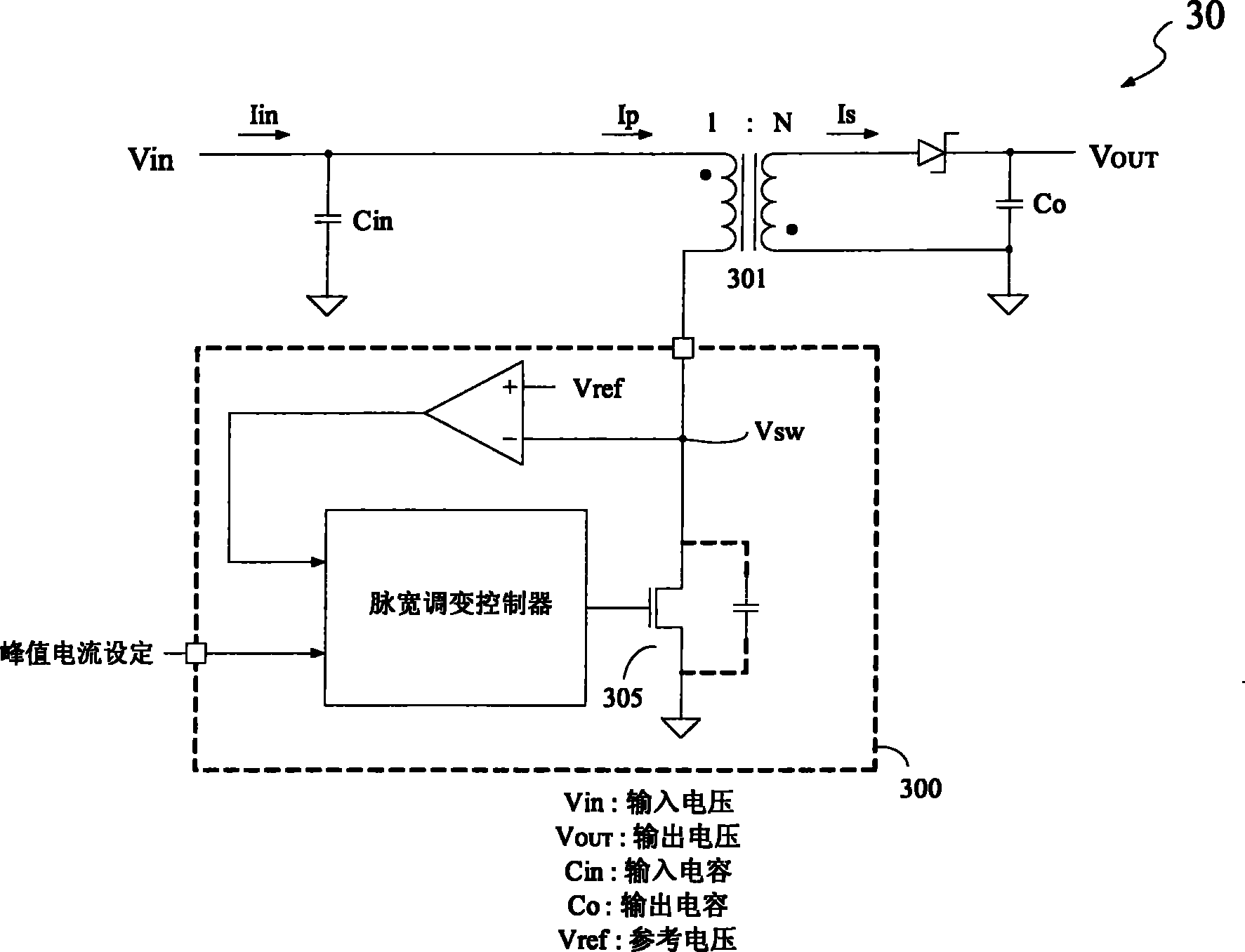
However, the charging device 30 still has the following disadvantages, for example: (1) when the power switch 305 is cut off, and the secondary side current Is of the transformer 301 drops to zero, the drain voltage Vsw of the power switch 305 drops to one due to resonance. When the reference voltage Vref is reached, the power switch 305 is turned on again. At this time, the ratio of the blank time Tb to the off-time Toff of the power switch 305 will be longer as the Vsw voltage is higher (please refer to Figure 4 ), because during the blank time Tb, the charging device 30 does not transmit the energy of the input terminal voltage Vin to the output terminal capacitor Co, so the overall charging time is longer and the charging efficiency is poor; (2) due to the addition of the blank time, the power The cut-off time Toff of the switch is relatively long and the switching frequency is low, so a larger transformer must be used; (3) Due to the low switching frequency, a larger input capacitor Cin is required to achieve a smaller average charging current Iin ripple ; (4) During the charging process, as the output terminal Vout voltage gets higher, the average charging current Iin cannot maintain a fixed value and will gradually decrease

Method used


Image

  • Charger with boundary mode control
  • Charger with boundary mode control
  • Charger with boundary mode control

Examples


Embodiment Construction

[0062] The invention discloses a charging device, in particular a charging device with boundary mode control. In order to make the description of the present invention more detailed and complete, the following description will be made in conjunction with the drawings.

[0063] refer to Figure 5 , is a circuit diagram of the charging device 50 disclosed in the first embodiment of the present invention. In this embodiment, the charging device 50 includes: a transformer 52 , a power switch 53 , a detection circuit 54 and a pulse width modulation controller 56 . Wherein, the transformer 52 further includes a primary coil 521 and a secondary coil 522 , each having a coil ratio of 1:N. The primary coil 521 is used to generate a magnetic field voltage, and the secondary coil 522 generates an induced magnetic field voltage by interacting with the primary coil. Furthermore, the detection circuit 54 further includes a capacitor 542 , a diode 544 , a current mirror 546 , a current so...


PUM


Abstract

The invention discloses a charging equipment provided with boundary mode control, comprising a transformer, a power switch, a detection circuit and a pulse width modulation controller; the power switch is connected with one end of a primary coil of the transformer in series; the detection circuit is electrically connected with the primary coil and the power switch for detecting the resonance of parasitic components of the power switch when the power switch is cut off, so as to provide a detection signal for the boundary control, the detection circuit includes an electric current mirror and a capacitor, the power source end of the electric current mirror is electrically connected with the other end of the primary coil, and one end of the capacitor is electrically connected with the power switch, the other end of the capacitor is electrically connected with the input end of the electric current mirror; and the pulse width modulation controller is used for generating a pulse width modulation signal to switch the power switch and leading the power switch to be conducted according to the detection signal.

Description

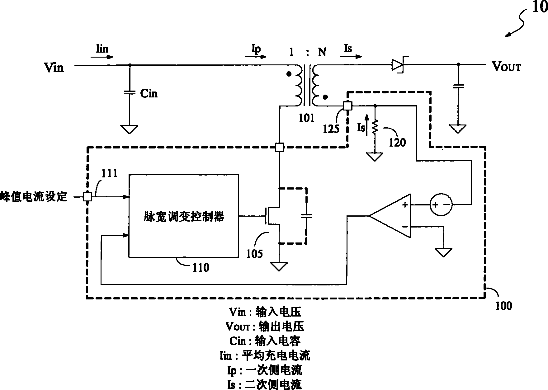
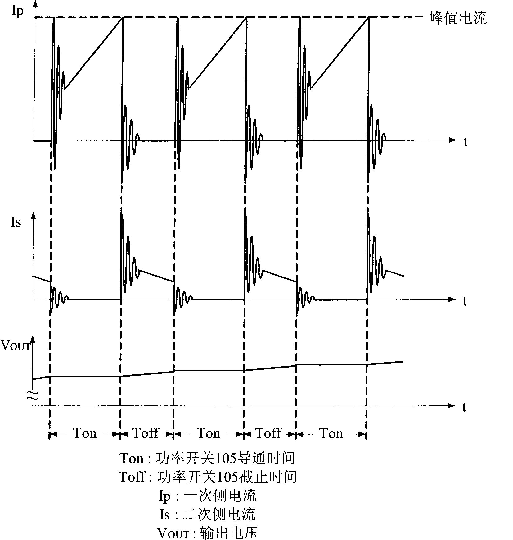
technical field [0001] The present invention relates to a charging device, in particular to a charging device with boundary mode control. Background technique [0002] In the known technology, there are generally two methods for charging control of a charging device. They are continuous conduction current mode control (Continuous Conduction Current Mode; CCM) and discontinuous conduction current mode control (Discontinuous Conduction Current Mode; DCM). [0003] figure 1 Shown is a charging device 10 with continuous conduction current mode (CCM) control in the known technology. When the power switch 105 is turned on, the primary coil current Ip of the transformer 101 will rise, and after the Ip current rises to the peak current setting value (in The peak current setting terminal 111 of the pulse width modulation controller 110 is set), and the power switch 105 will be turned off. [0004] After the power switch 105 is turned off, the secondary side current Is gradually de...

Claims


Application Information

Patent Timeline
Patent Type & Authority Patents(China)
IPC IPC(8): H02J7/00H02J15/00H02M3/335
Inventor 庄明男朱益杉王昱斌
Owner LEADTREND TECH
Learn More