Method in connection with a reel-up of a fibre-web machine

A fiber web machine and web technology, applied in the direction of winding strips, thin material handling, transportation and packaging, etc., can solve the problems of hindering the machine, increasing costs, blocking, etc., to reduce surface cracks and achieve a large amount of cost Effect

Inactive Publication Date: 2009-03-04
METSO PAPER INC
View PDF0 Cites 2 Cited by
  • Summary
  • Abstract
  • Description
  • Claims
  • Application Information

AI Technical Summary

Problems solved by technology

In the case where the surface layer of the web roll is held firmly on a full roll by a high electrical charge, there is a problem as the charge can discharge from the roll in an uncomfortable or dangerous way through the operator to the machine frame or building objects, so this high charge prevents work close to the machine, such as sampling
A disadvantage of this known arrangement is the increased costs caused by pressing devices such as brushes or rollers, the marking of the web and the space required by these devices
A problem with these arrangements known in the prior art has proven to be that surface-bound material can build up and dry out at the nozzle of the supply pipe, causing it to clog

Method used


Image

  • Method in connection with a reel-up of a fibre-web machine
  • Method in connection with a reel-up of a fibre-web machine
  • Method in connection with a reel-up of a fibre-web machine

Examples


Embodiment Construction

[0041] In the drawings and descriptions associated with the drawings, the same reference numerals are used to denote parts corresponding to each other unless otherwise indicated.

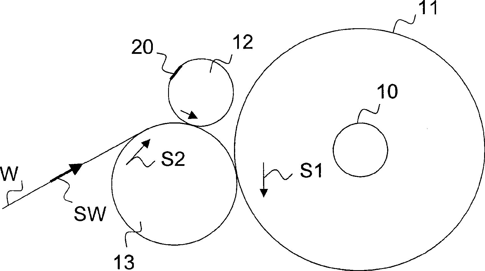
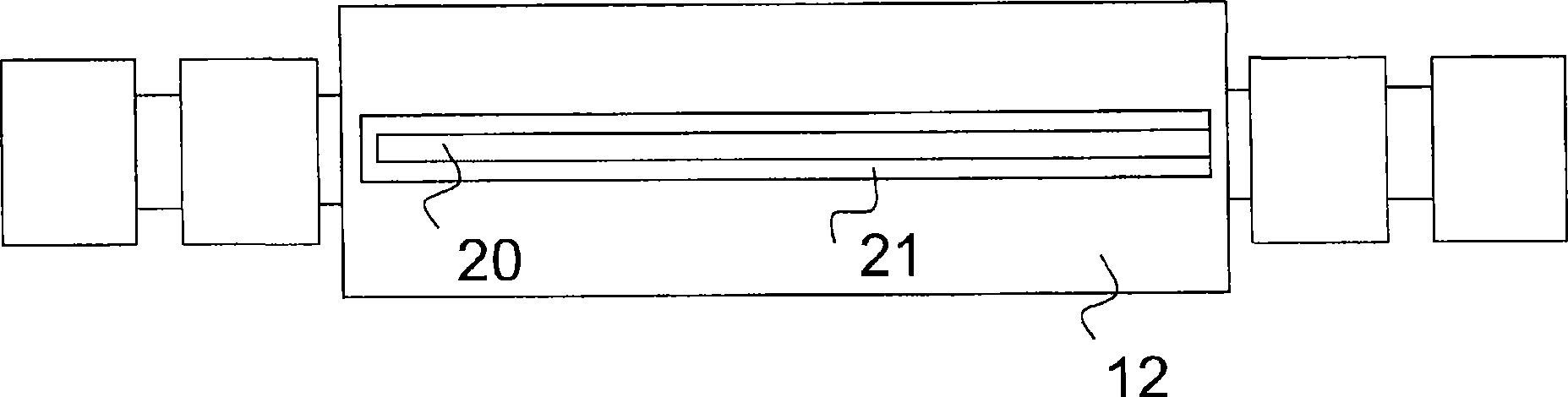
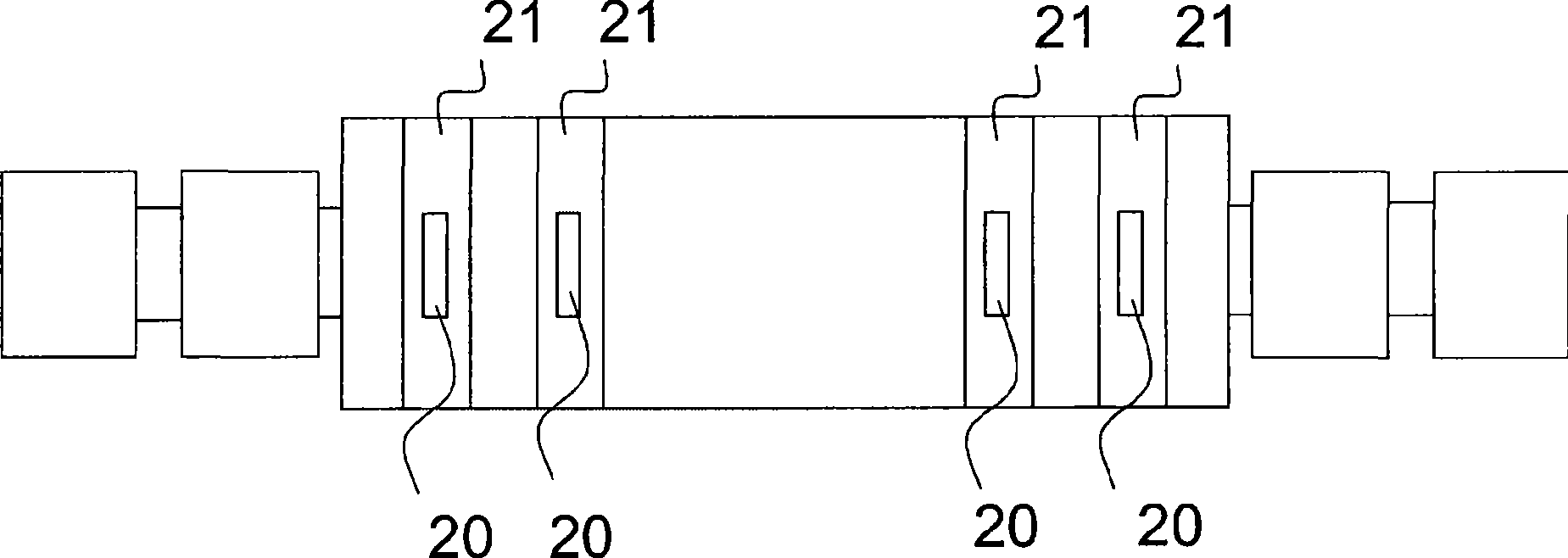
[0042] in accordance with figure 1 There is a web roll 11 in the arrangement, ie a fully wound machine roll 11 around the take-up shaft 10 . The reel is indicated with reference numeral 13 and in order to form the next web roll to be wound up on the new roll, the new take-up shaft 12 is moved to a standby position in relation to the reel 13 . Arrows S1 and S2 show the direction of rotation of the machine roll 11 being fully wound and the direction of rotation of the mandrel 13, and arrow SW shows the direction of travel of the web W. According to a preferred embodiment of the present invention, one or more double-sided adhesive tapes 20 are fixed to the surface of the new take-up shaft 12 to be moved to the standby position before the new take-up shaft 12 is moved to the standby position. Adhesive...


PUM

PropertyMeasurementUnit
bond strengthaaaaaaaaaa

Abstract

The invention relates to a method in connection with a change process of a reel-up of a fibre-web machine, which method is applied when performing a change of reeling of a web (W) from a web roll (11) being completed to a new web roll for reeling the next roll around a reeling shaft (12). In the method, for fastening the surface layer/surface layers of the web roll (11) to the web roll (11) beingcompleted, at least one two-sided tape (20) is adhered from its one side to the web (W) being passed to the web roll (11) being completed or to the surface of the web roll (11) and said tape (20) is adhered from its other side to the surface of the web roll (11) being completed/to the surface of the web (W) being reeled onto the web roll (11) being completed due to the effect of a reeling nip between the reel drum (13) and the web roll (11) or a pressing-roll nip between the web roll (11) and a pressing roll (14) or due to the effect of the tightness (T) of the web.

Description

technical field [0001] The invention relates to a method according to the preamble of claim 1 . Background technique [0002] It is known from the prior art that, in fiber web machines such as paper and board machines, coiling is used in relation to which fibrewebs (fibreweb) produced by fiber web machines such as paper / board machines Coiled onto machine rolls as a full width web for further processing. By surface pull in the take-up nip between the mandrel and the web roll being formed or by using a central drive, the web is wound up around a take-up shaft such as a reel / roll, whereby the take-up shaft is also set There are drives. In coiling, when a machine roll is about to be full, a roll change needs to be performed to start a new machine roll coil and the full machine roll needs to be removed from the coil. In the lap change process, the web is cut, whereby one end of the web is connected to a fully wound machine roll and the other end of the web is directed around a...

Claims


Application Information

Patent Timeline
Patent Type & Authority Applications(China)
IPC IPC(8): B65H19/29
CPCB65H2408/236B65H2301/414422B65H19/29B65H19/22
Inventor 亚里·蒂塔汉努·卡苏拉彼得里·兰内斯
Owner METSO PAPER INC
Why Eureka
Try Eureka