Pipe shaped sponges shaping conjunction machine

A sponge and tube-shaped technology, which is applied in the field of tube-shaped sponge forming and fitting machines, can solve problems such as production line capacity not meeting requirements, product reliability being low, wire loss of protection, etc., achieving easy disassembly and repair, high degree of automation, and production fast effect

Inactive Publication Date: 2009-03-11
SUZHOU SONAVOX ELECTRONICS
View PDF0 Cites 0 Cited by
  • Summary
  • Abstract
  • Description
  • Claims
  • Application Information

AI Technical Summary

Problems solved by technology

[0003] Among the above-mentioned production methods, the cost of manpower is high, and the speed cannot meet the requirements of modern high-speed production. The production capacity of the pr

Method used


Image

  • Pipe shaped sponges shaping conjunction machine
  • Pipe shaped sponges shaping conjunction machine
  • Pipe shaped sponges shaping conjunction machine

Examples


Embodiment Construction

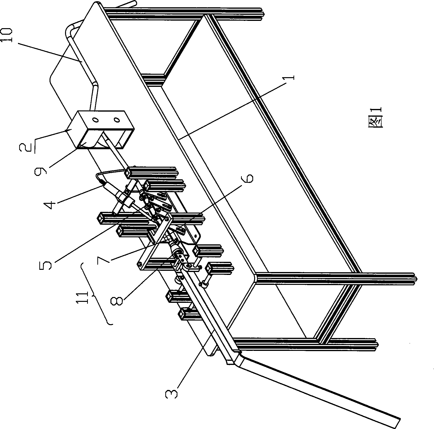
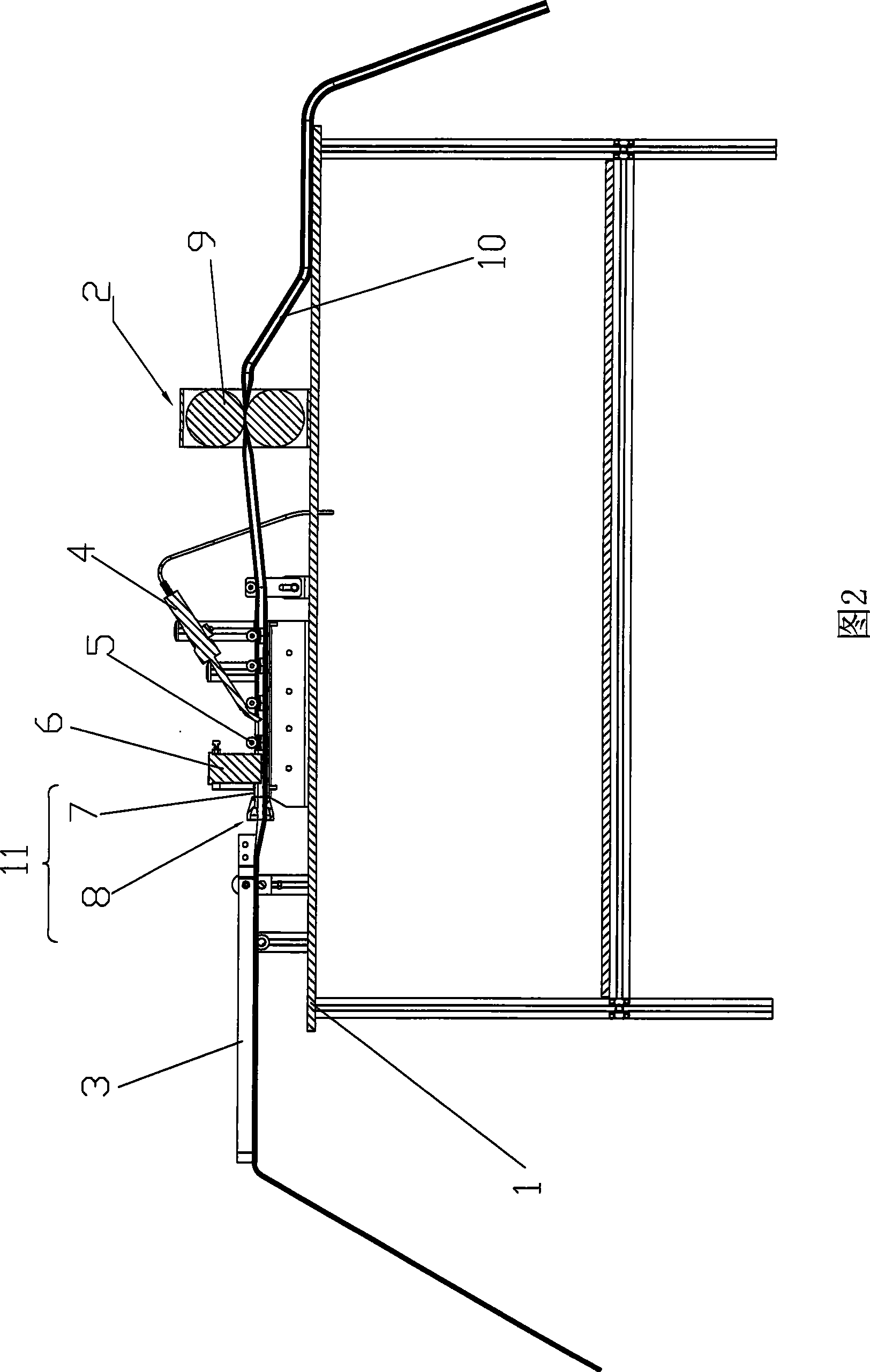
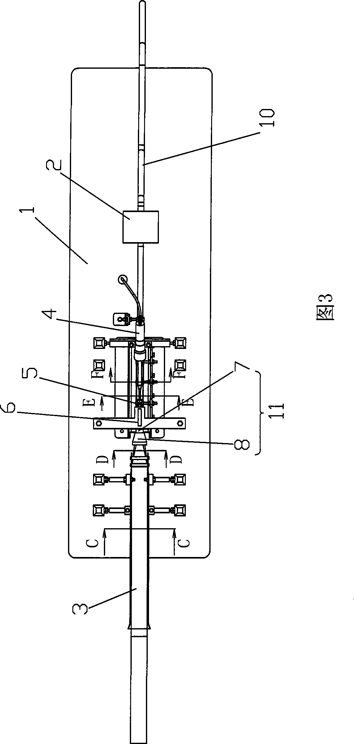
[0017] See Figure 1 to Attached Figure 7 , a tubular sponge forming and fitting machine, which includes: a frame 1, a throat-shaped tube 11 arranged on the frame 1 from back to front, at least partially extending into the throat-shaped tube 11 guide plate 6, electric soldering iron 4, and traction mechanism 2 for pulling the sponge tube, as shown in the figure, the traction mechanism 2 includes two rollers 9 with opposite directions of rotation, and the processed tubular sponge 10 is positioned between the two rollers. Pass between 9, rely on a pair of rollers 9 to constantly pull the sponge 10 forward, so that the strip sponge in the feeding position moves forward along the feeding guide rail 3. In accompanying drawing 2, the right side is before, and the left side is after.

[0018] In this embodiment, the throat-shaped pipe 11 includes a circular tube 8 whose diameter gradually decreases from the rear to the front and a circular tube 7 connected to the front end of the ci...


PUM


Abstract

A tubular sponge molding conjugating machine comprises a machine frame, throat tubes which are arranged on the machine frame from back to front in sequence, guide plates with at least a part extending into the throat tubes, an electric iron and a draughting mechanism which is used for draughting the sponge tube; the throat tubes comprise a section of cone tubes with decreasing calibers from back to front; the front and back of the electric iron are provided with pinch rollers. With the invention, the problems in the prior art can be solved and a production pattern of a sponge tube with high reliability, low demands of labors and simple structure is provided.

Description

technical field [0001] The invention relates to a tubular sponge forming and fitting machine for processing strip sponges into sponge tubes. Background technique [0002] In automotive electronic circuits, due to the high requirements on the wear resistance of the wires, it is necessary to add a layer of sponge to the outside of the wires to reduce friction and vibration between the wires. The method adopted in the prior art is to manually wrap the sponge around the outside of the wire, and finally use glue to bond the interface. [0003] Among the above-mentioned production methods, the cost of manpower is high, and the speed cannot meet the requirements of modern high-speed production. The production capacity of the production line cannot meet the requirements. At the same time, the reliability of the products produced is not high. breakage, making the wire vulnerable to breakage due to loss of protection. Contents of the invention [0004] The object of the present in...

Claims


Application Information

Patent Timeline
IPC IPC(8): B29C53/36B29C53/80B29L23/00
Inventor 潘惠华
Owner SUZHOU SONAVOX ELECTRONICS
Why Eureka
Try Eureka