Self-adjusting electric speed differential

An electronic differential and self-adjusting technology, applied in the field of electric vehicle systems, can solve the problems of inflexible turning, bulky, high cost, etc.

Inactive Publication Date: 2009-03-11
ZAOZHUANG UNIV
View PDF5 Cites 14 Cited by
  • Summary
  • Abstract
  • Description
  • Claims
  • Application Information

AI Technical Summary

Problems solved by technology

Existing electric vehicles (electric vehicles, road-type electric tricycles) use mechanical differentials, which are heavy and costly.

Method used


Image

  • Self-adjusting electric speed differential
  • Self-adjusting electric speed differential
  • Self-adjusting electric speed differential

Examples


Embodiment Construction

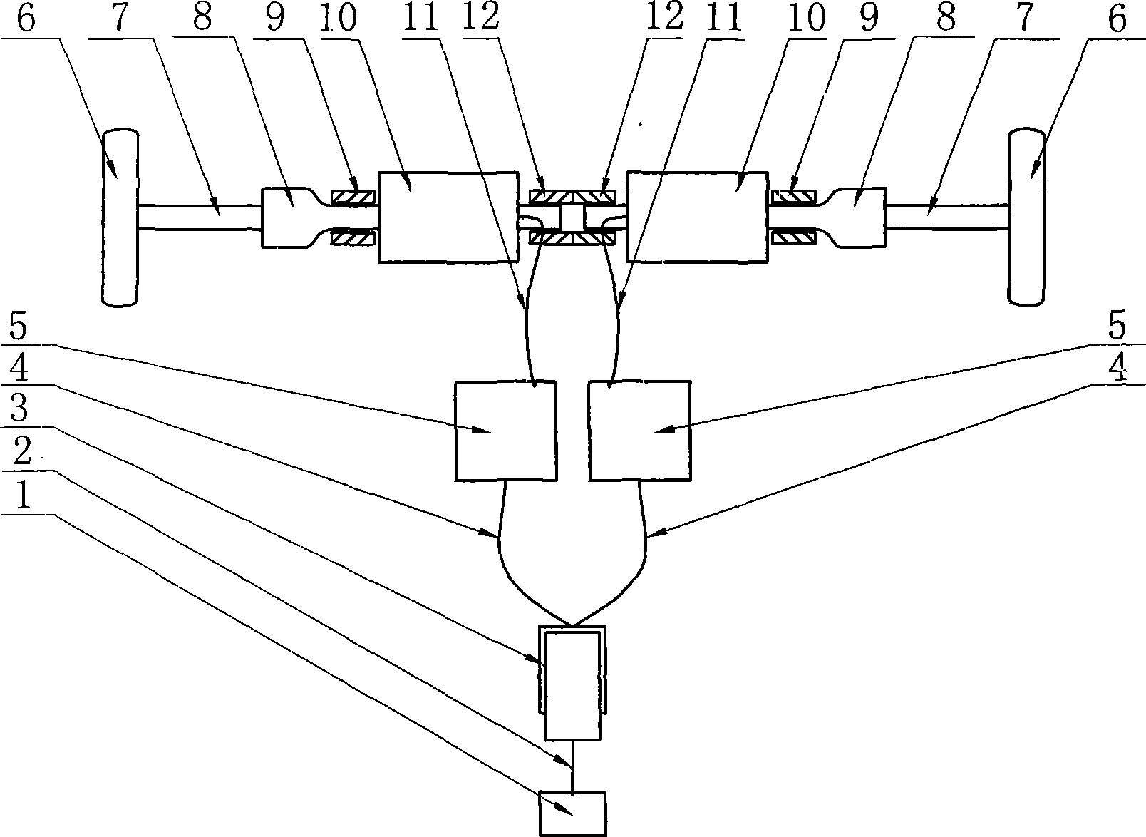
[0020] The self-adjusting electronic differential of the present invention, such as figure 1 As shown, the accelerator 3 is composed of an accelerator pedal 1, an accelerator pedal connecting rod 2 and an accelerator body. The accelerator signal line is divided into two inner and outer ones, which are respectively connected with the inner and outer drive motors 10 to control the operation of the motor. The inner and outer driving wheels 6 are respectively driven by the inner and outer driving wheel transmission shafts 7, and the inner and outer driving wheel transmission shafts 7 are connected with the universal sleeves 8 of the inner and outer driving wheel transmission shafts through tooth-shaped splines. The shaft of the universal sleeve 8 of the wheel transmission shaft is placed in the bearing 9 of the universal sleeve of the inner and outer drive wheel transmission shafts, and the shaft of the universal sleeve 8 of the inner and outer drive wheel transmission shafts is co...


PUM


Abstract

The invention relates to a self-regulating electronic differential mechanism which is an electronic control system of an electric car and is mainly applied to a dual-motor independent driving mode electric car. Two driving wheels are respectively driven by two motors directly. The driving motors are respectively controlled by two controllers with the same specification. The dual-motor independent and direct driving mode is realized and the self-regulating function of the electric differential is realized. The two controllers are controlled by an accelerator so that the two motors work under the same power and voltage. Due to the characteristics of the motors, the electric differential self-regulating function is realized through the regulation of different slipping rates and the flow limiting function of the controllers. As the driving torque of an internal driving wheel is larger than the external driving torque, therefore, different slipping rates appear and understeer is represented.

Description

technical field [0001] The invention relates to an electric vehicle system, in particular to an electronic control system of the electric vehicle. Background technique [0002] The patent application number is 02136498.2, and the invention name is "four-wheel electronic differential steering control system" discloses a four-wheel electronic differential steering control system, including a motor (1), a brake mechanism (7), a steering mechanism (8 ) and acceleration switch (5), it also includes motor controller (2), angular displacement sensor (6), speed sensor (3) and central processing unit (4), described motor controller (2), angle Displacement sensor (6), rotational speed sensor (3), brake mechanism (7), steering mechanism (8) and acceleration switch (5) are respectively connected to each corresponding port of central processing unit (4), and this central processing unit collects each sensor and on-board components, and calculate the corresponding target speed of each wh...

Claims


Application Information

Patent Timeline
IPC IPC(8): B60L15/20B60K7/00B60K1/02
CPCY02T10/648Y02T10/646Y02T10/64Y02T10/72
Inventor 刘宗锋
Owner ZAOZHUANG UNIV
Why Eureka
Try Eureka