Guide ball-pin assembly

A technology of guiding balls and ball pins, applied in steering mechanism, steering rod, transportation and packaging, etc., can solve the problems of short service life, steering wheel trembling, easy radial loosening, etc., achieves less wear, increased friction surface, extended The effect of service life

Inactive Publication Date: 2009-03-11
沈百庆
View PDF0 Cites 2 Cited by
  • Summary
  • Abstract
  • Description
  • Claims
  • Application Information

AI Technical Summary

Problems solved by technology

The ball pin design of the traditional guide ball pin assembly generally adopts a spherical or cylindrical shape, and the function of only rotating can be achieved through the matching shape of the ball seat and the shell. The function of the ball pin not only needs to rotate and swing, but also needs to bear pull The guide ball pin is no exception to the pressure load (although there is no swing). The traditional guide ball pin assembly needs to be subjected to long-term tension and pressure during use, resulting in large wear, short service life, and easy radial looseness. Steering wheel shakes after being loosened, and more seriously, it will cause resonance of the whole vehicle

Method used


Image

  • Guide ball-pin assembly

Examples


Embodiment 1

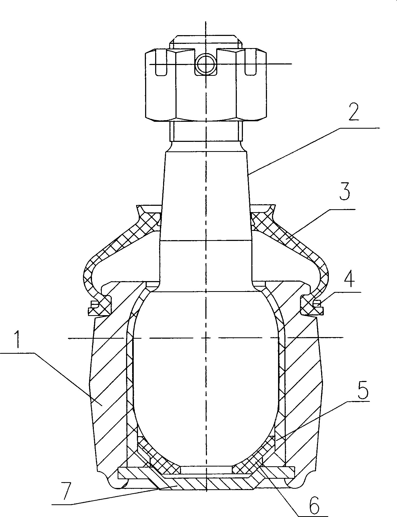
[0010] like figure 1 The invention shown is a guide ball pin assembly, including a housing 1, a ball seat installed in the housing 1 and a guide ball pin 2 installed in the ball seat, and the ball seat is installed in the housing 1 The large ball seat 5 inside is composed of the small ball seat 6 installed at the bottom of the large ball seat 5. The large ball seat 5 and the small ball seat 6 are combined to form a spherical cavity that matches the guide ball pin 2. The cover plate 7 is installed on the small ball seat. Below the ball seat 6, the cover plate 7 compresses the large ball seat 5 and the small ball seat 6 in the housing. The guide ball pin 2 is connected to one end of the dust cover 3, and the other end of the dust cover 3 is installed on the housing 1 through the collar 4. The guide ball pin 2 adopts a column type in which both ends are hemispherical and the middle is a cylindrical tube. ball pin. Large ball seat 5 and small ball seat 6 are used in cooperation ...


PUM


Abstract

The invention discloses a guidance ball pin assembly which comprises a casing body, a ball seat which is arranged in the casing body and a guidance ball pin which is arranged in the ball seat, wherein, the ball seat consists of a big ball seat that is arranged in the casing body and a small ball seat that is arranged on the bottom of the big ball seat; a spherical hollow cavity which is matched with the guidance ball pin comprises the big ball seat and the small ball seat; a cover plate is arranged below the small ball seat; dustproof covers are respectively arranged at both sides of the guidance ball pin; other ends of the dustproof covers are arranged on the casing body through a clamp ring; the guidance ball pin adopts a ball pin of column jacket type, wherein, both ends of the column jacket type ball pin are spherical and the middle part of the column jacket type ball pin is a cylinder tube; and synthetic resin is adopted as the raw material of the small ball seat. The invention has double excellences of excellent rotation resistance and tensile pressure resistance and can guarantee the good operational stability and the ride comfort of a whole vehicle.

Description

technical field [0001] The invention relates to a guide ball pin assembly. Background technique [0002] The guide ball pin assembly structure is a ball joint of the automobile steering system, which is used in a special tie rod mode for the front independent suspension. The ball pin design of the traditional guide ball pin assembly generally adopts a spherical or cylindrical shape, and the function of only rotating can be achieved through the matching shape of the ball seat and the shell. The function of the ball pin not only needs to rotate and swing, but also needs to bear pull The guide ball pin is no exception to the pressure load (although there is no swing). The traditional guide ball pin assembly needs to be subjected to long-term tension and pressure during use, resulting in large wear, short service life, and easy radial loosening. After loosening, the steering wheel shakes, and more seriously, it will cause the whole vehicle to resonate. Contents of the inventi...

Claims


Application Information

Patent Timeline
Patent Type & Authority Applications(China)
IPC IPC(8): B62D7/18
Inventor 沈百庆
Owner 沈百庆
Why Eureka
Try Eureka