Power unit

A technology of power unit and engine, applied in the direction of motor vehicles, transmissions, electric scooters, etc., can solve the problems of buffering and operation stability, large moving range, etc., to improve driving performance, ensure maintenance, and suppress vibration. Effect

Inactive Publication Date: 2009-03-11
HONDA MOTOR CO LTD
View PDF1 Cites 4 Cited by
  • Summary
  • Abstract
  • Description
  • Claims
  • Application Information

AI Technical Summary

Problems solved by technology

In other words, in the general swing mode of the device, the rear of the crankshaft has a larger movement stroke than the front of the crankshaft, which has a great influence on cushioning and operational stability.

Method used


Image

  • Power unit
  • Power unit
  • Power unit

Examples


Embodiment Construction

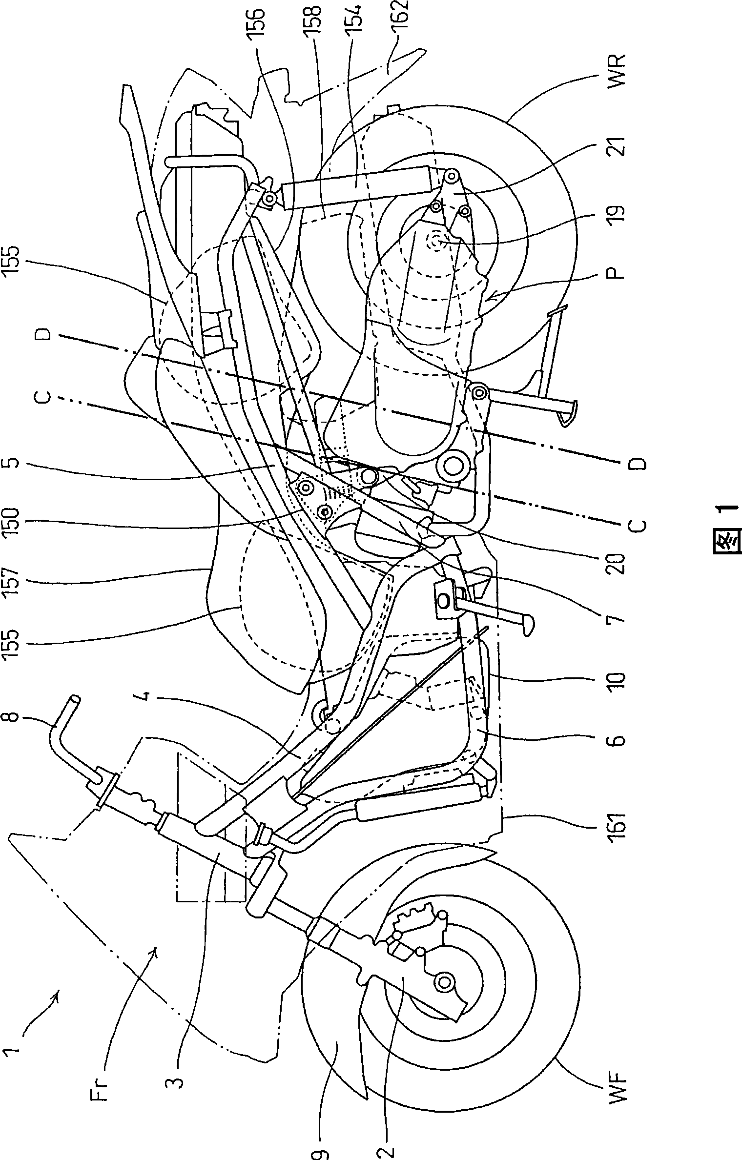
[0057] FIG. 1 is a side view of a motorcycle 1 equipped with a power unit P according to an embodiment of the present invention, and FIG. 2 is an enlarged rear view of the motorcycle 1 . In FIG. 1 , the frame Fr of the motorcycle 1 includes: a head tube 3 that rotatably supports a front fork 2 ; a main frame 4 extending rearward and downward from the head tube 3 ; A pair of left and right rear frames 5 connected in parts and extending rearward and upward; a lower frame 6 extending downward from the head pipe 3 and bent backward and connected to the lower end of the main frame 4; The middle frame 7 of the middle part. The front wheel WF is pivotally supported on the lower end of the front fork 2 , the steering handle 8 is connected to the top of the front fork 2 , and the front fender 9 covering the top of the front wheel is supported by the front fork 2 . A fuel tank 10 is provided between the main frame 4 and the lower frame 6 .

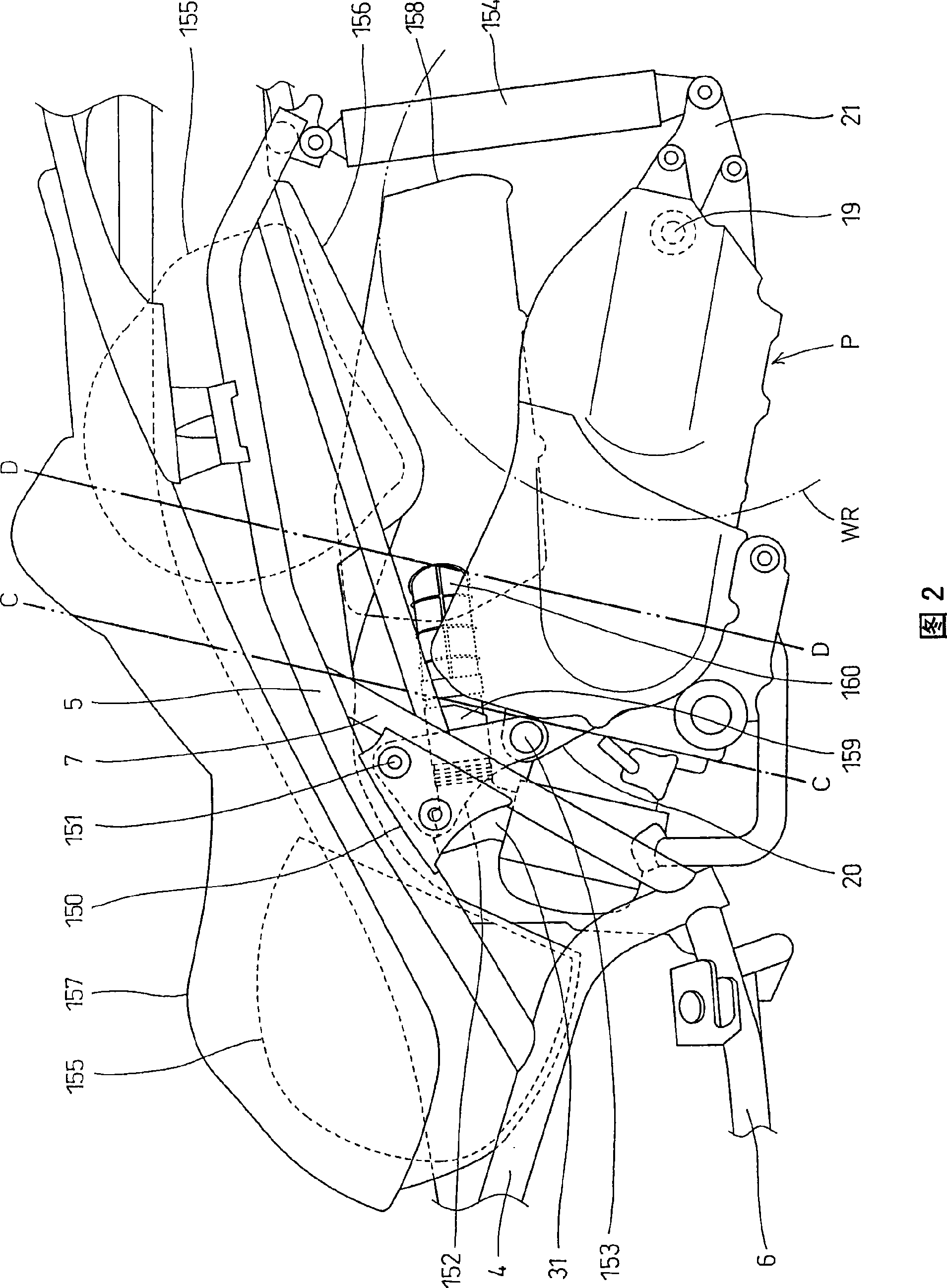
[0058] Referring to FIG. 2 together, pivot ...


PUM


Abstract

The invention provides a power unit with the following characteristic features. The power unit includes: an engine that includes a cylinder block, a crankcase, and a balancer; a transmission casing that extends rearwards from the crankcase of the engine; a V-belt type continuously variable transmission installed in the transmission casing and transmitting the drive power from the engine to a drive wheel; and an electric motor for drive-pulley control that controls the width of the groove of a drive pulley in the V-belt type continuously variable transmission by means of a reduction gear mechanism for drive-pulley control unit. In the power unit, the engine has to be compact in size while the placement of the components of the power unit has to be well-balanced. In the provided power unit, when viewed from a side, the electric motor for drive-pulley control, the reduction gear mechanism for the drive-pulley control unit, and the center of the balancer are placed between a joint plane where the cylinder block is coupled to the crankcase and a plane which passes on the center of the crankshaft and which is parallel to the joint plane.

Description

technical field [0001] The invention relates to the arrangement of heavy objects in a power unit, and the power unit is composed of an engine and a transmission. Background technique [0002] In a conventional power unit, a drive pulley control motor, a drive pulley control portion reduction gear mechanism, and a balancer are arranged behind the crankshaft (for example, refer to Patent Document 1). In the arrangement of such heavy objects, on the one hand, the engine must be compactly formed, and on the other hand, it is necessary to consider a good arrangement of the weight balance. That is, in the usual swing mode of the device, the movement stroke of the rear of the crankshaft is larger than that of the front of the crankshaft, which has a great influence on cushioning and operational stability. For this reason, it is desirable that each weight of the constituent members of the power unit be arranged as far forward as possible of the crankshaft. [0003] Patent Document...

Claims


Application Information

Patent Timeline
Patent Type & Authority Applications(China)
IPC IPC(8): F02B61/02F16H9/00F16H9/18B60K17/04B60K17/06
CPCB62K2202/00F16H9/18
Inventor 石川秀男森田豪池田直机
Owner HONDA MOTOR CO LTD
Why Eureka
Try Eureka