Dragging device with high starting performance induction motor and frequency transformer cooperatively running
A technology of induction motor and starting performance, which is applied in the direction of AC motor control, starter parts, electrical components, etc., can solve the high problems of motors and frequency converters, achieve high safety factor operation, ensure optimal efficiency, and have obvious energy-saving effects Effect
- Summary
- Abstract
- Description
- Claims
- Application Information
AI Technical Summary
Problems solved by technology
Method used
Image
Examples
specific Embodiment approach 1
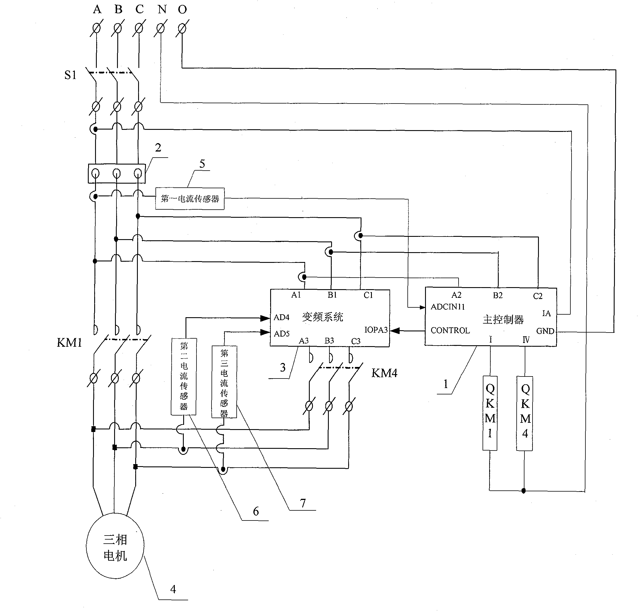
[0010] Specific embodiment 1: Referring to Fig. 1 to illustrate this specific embodiment, the driving device for the joint operation of a high-starting performance induction motor and a frequency converter includes: a first AC contactor KM1, a fourth AC contactor KM4, a frequency conversion system 3, The three-phase motor 4, the first current sensor 5, the second current sensor 6, the third current sensor 7 and the main controller 1, the A-phase static terminal of the first AC contactor KM1, and the B-phase static terminal of the first AC contactor KM1 terminal and the C-phase static terminal of the first AC contactor KM1 are respectively connected with the A-phase power input terminal A1, the B-phase power input terminal B1 and the C-phase power input terminal C1 of the frequency conversion system 3, and the A-phase power of the frequency conversion system 3 The output terminal A3, the B-phase power output terminal B3 and the C-phase power output terminal C3 are respectively c...
specific Embodiment approach 2
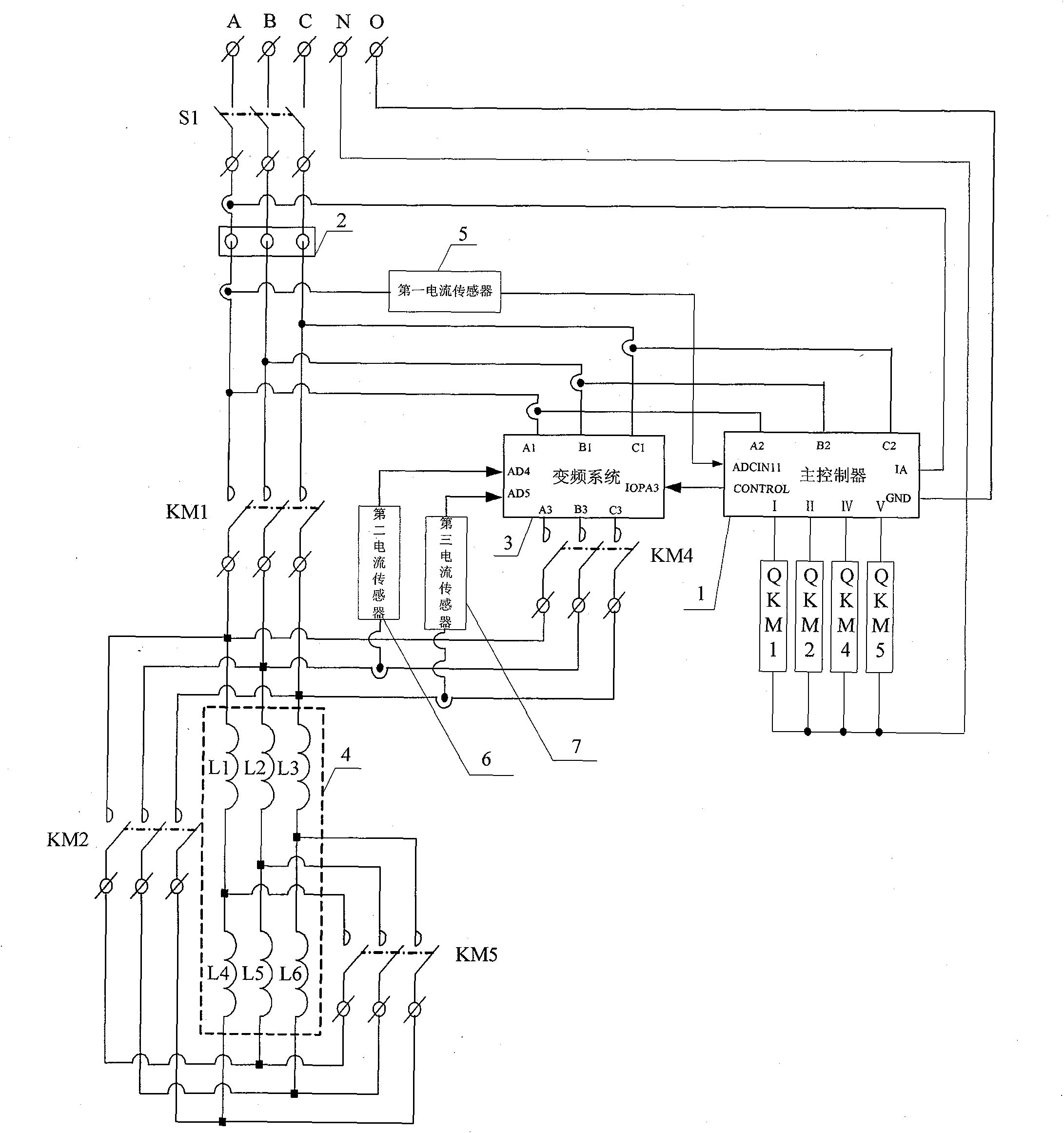
[0013] Specific embodiment two: This specific embodiment is described with reference to Fig. 2, and the difference between this embodiment and specific embodiment one is that it also includes the second AC contactor KM2 and the fifth AC contactor KM5, and the windings of its three-phase motor 4 Including: motor winding L1, motor winding L2, motor winding L3, motor winding L4, motor winding L5 and motor winding L6, the ends of the motor winding L1, motor winding L2 and motor winding L3 are respectively connected to the motor winding L4, motor winding L5 It is connected to the first end of the motor winding L6, and the A-phase static end of the second AC contactor KM2, the B-phase static end of the second AC contactor KM2, and the C-phase static end of the second AC contactor KM2 are respectively connected to the motor winding The head end of L1, the head end of motor winding L2 and the head end of motor winding L3 are connected, the A-phase moving end of the second AC contactor ...
specific Embodiment approach 3
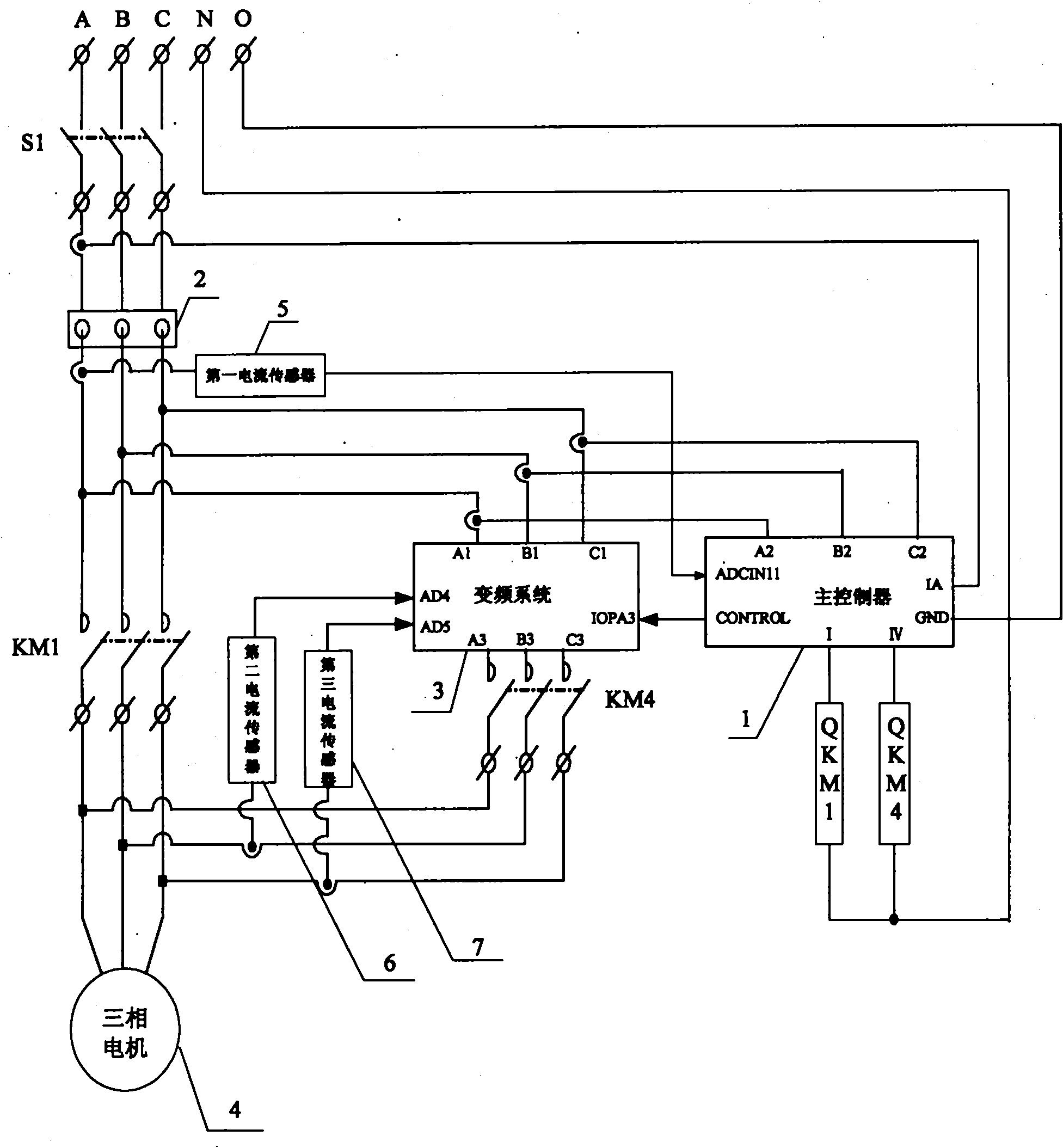
[0015]Specific embodiment three: the difference between this embodiment and specific embodiment two is that it also includes: a motor integrated protector 2 and an air circuit breaker S1, and the three-phase power supply is connected to the A-phase static end and the air circuit breaker of the air circuit breaker S1 respectively. The B-phase static end of the switch S1 is connected to the C-phase static end of the air-break switch S1, the A-phase moving end of the air-breaking switch S1, the B-phase moving end of the air-breaking switch S1, and the C-phase moving end of the air-breaking switch S1 Respectively connected to the A-phase current input end of the integrated motor protector 2, the B-phase current input end of the integrated motor protector 2 and the C-phase current input end of the integrated motor protector 2, the A-phase current input end of the integrated motor protector 2 The output terminal, the B-phase current output terminal and the C-phase current output term...
PUM
 Abstract
Description
Claims
Application Information
 - R&D
- Intellectual Property
- Life Sciences
- Materials
- Tech Scout
- Unparalleled Data Quality
- Higher Quality Content
- 60% Fewer Hallucinations
Browse by: Latest US Patents, China's latest patents, Technical Efficacy Thesaurus, Application Domain, Technology Topic, Popular Technical Reports.
© 2025 PatSnap. All rights reserved.Legal|Privacy policy|Modern Slavery Act Transparency Statement|Sitemap|About US| Contact US: help@patsnap.com


