Waste heat recovery apparatus

A control device and superheat technology, applied to engine components, machines/engines, internal combustion piston engines, etc., can solve problems such as difficult starting, impact, and durability reduction of the Rankine cycle

Inactive Publication Date: 2009-03-18
DENSO CORP +1
View PDF2 Cites 37 Cited by
  • Summary
  • Abstract
  • Description
  • Claims
  • Application Information

AI Technical Summary

Problems solved by technology

[0007] At the start of the Rankine cycle, when the working fluid flows into the expander from the heat exchanger for heating, a sharp pressure difference is generated between the inlet and outlet of the expander , correspondingly, a large force acts on the sliding part of the expander, which is affected resulting in reduced durability
Therefore, it is difficult to start a stable Rankine cycle

Method used


Image

  • Waste heat recovery apparatus
  • Waste heat recovery apparatus
  • Waste heat recovery apparatus

Examples


no. 1 approach

[0045] Hereinafter, regarding the first embodiment of the present invention, refer to Figure 1 to Figure 11 Be explained.

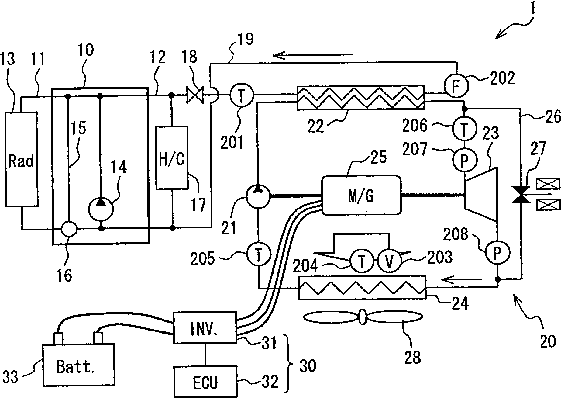
[0046] figure 1 It is a schematic diagram showing the whole system of the waste heat utilization device 1 having the Rankine cycle 20 . Such as figure 1 As shown, the waste heat utilization device 1 of this embodiment is applied to, for example, a vehicle that uses the engine 10 as a drive source.

[0047] The engine 10 is a water-cooled internal combustion engine. The engine is provided with a cooler circuit 11 that cools the engine 10 by circulation of engine cooling water, and a heater circuit 12 that heats conditioned air using cooling water (warm water) as a heat source.

[0048] A cooler 13 is arranged in the cooler circuit 11 . The cooler 13 cools the cooling water circulated by the warm water pump 14 by exchanging heat with the outside air. The warm water pump 14 may be an electric pump or a mechanical pump. A heater 22 of a Rankine cycle 20...

no. 2 approach

[0125] Next, regarding the second embodiment of the present invention, refer to Figure 12 , Figure 13 Be explained. In addition, in this embodiment, the steps common to the first embodiment are denoted by the same symbols as in the first embodiment, and the following description will focus on the parts different from the first embodiment.

[0126] Figure 12 It is a flowchart explaining the detail of Rankine operation control (S4) of this embodiment. In this embodiment, the highest and lowest rotational speed setting step (S411) of the Rankine operation control (S4) is different from the above-mentioned first embodiment, and other device configurations and controls are the same. Therefore, the maximum and minimum rotational speed setting step (S411) will be described in detail, and other descriptions will be omitted.

[0127] Such as Figure 12 As shown, in step S411, the increase or decrease of the maximum rotational speed Nmax_s of the expander 23 is determined accord...

no. 3 approach

[0143] Hereinafter, for the third embodiment of the present invention, refer to Figure 17 -20C for explanation.

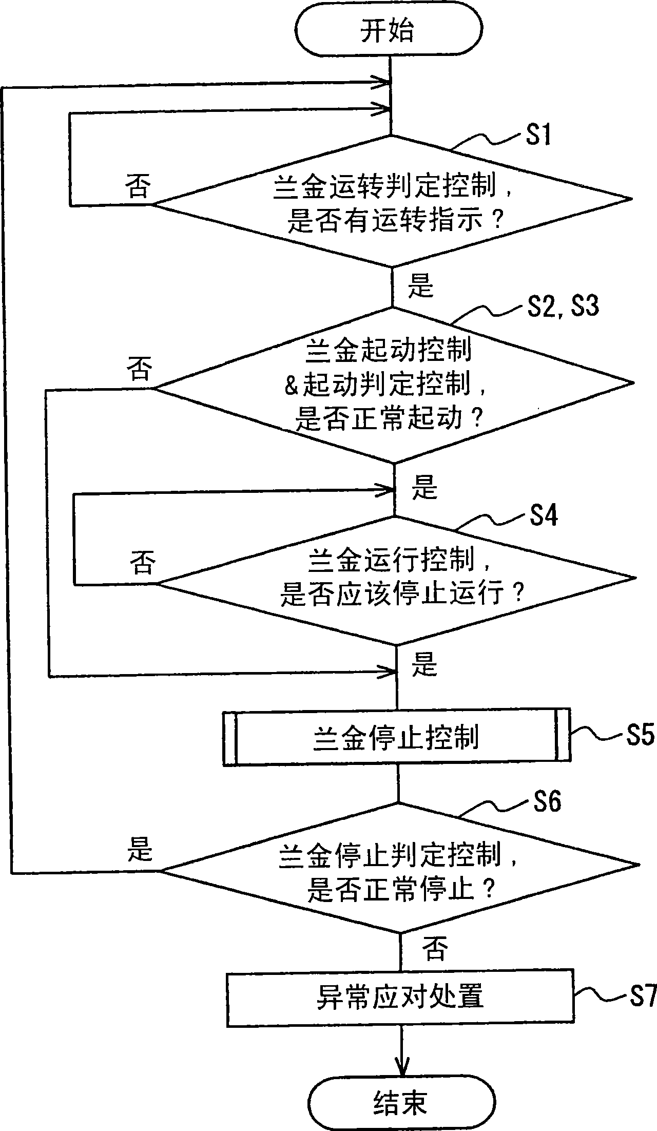
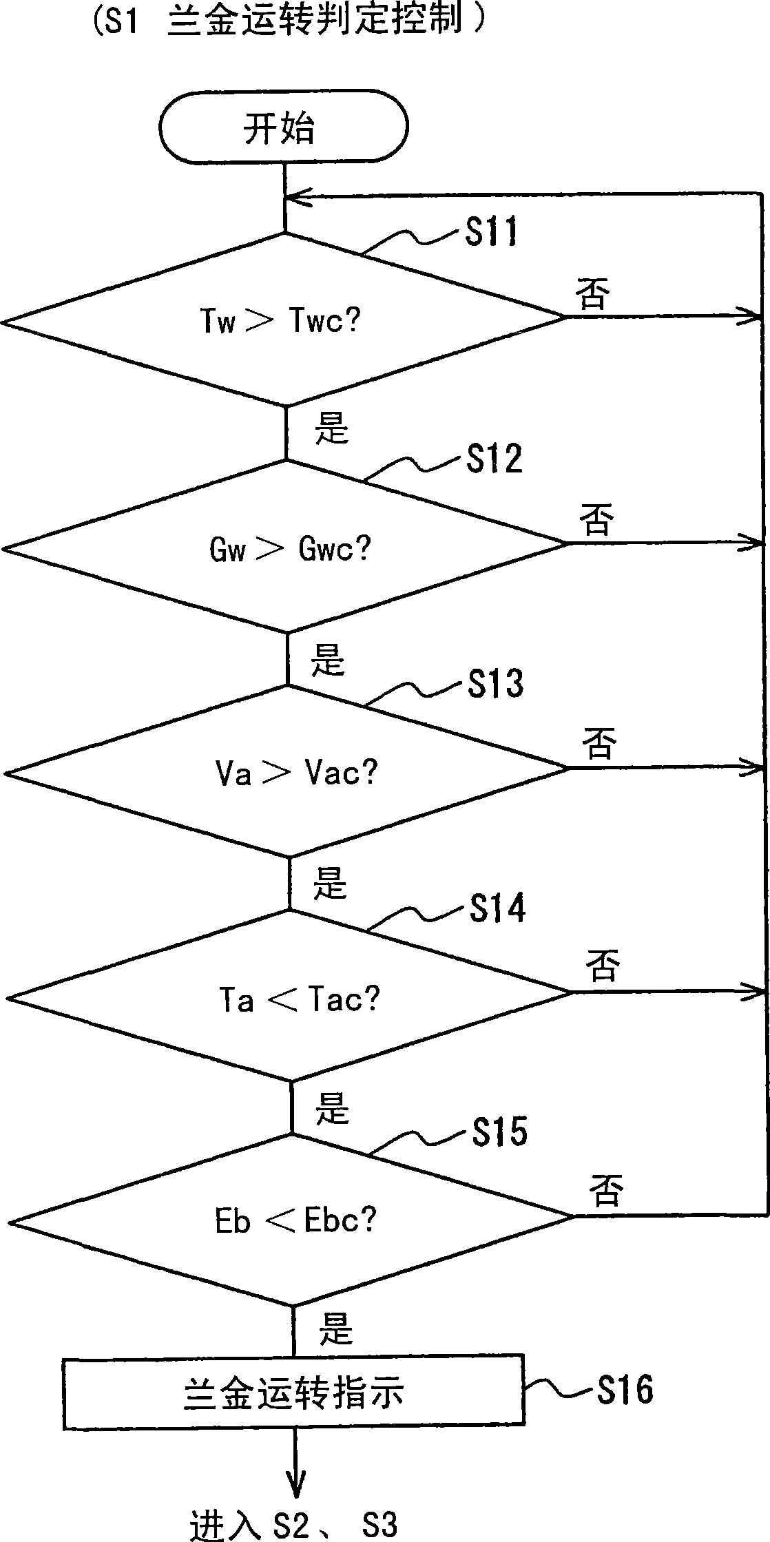
[0144] Figure 17 It is a schematic diagram showing the whole system of the waste heat utilization device 1 having the Rankine cycle 20 according to the present embodiment. Figure 18 It is a flowchart showing the control (Rankine start control S2a) at the start of the Rankine cycle 20, which is the characteristic part of this embodiment, Figure 19 It is a time chart showing the pressure difference of the expander and the rotational speed of the pump expander from the start of the Rankine cycle 20 to normal control, Figure 20A -20C is a schematic diagram showing the refrigerant flow rate at each part when the Rankine cycle 20 is started.

[0145]In this embodiment, the pump 21 is connected to the generator 25 and the expander 23 through the same drive shaft. Hereinafter, the same reference numerals are assigned to the same parts as those of the first embodim...


PUM


Abstract

A waste heat recovery apparatus includes a Rankine cycle (20) which includes a heater (22) for heating an operation fluid by waste heat from a heat-generating device (10), an expansion unit (23) for converting energy of expansion of the operation fluid flowing out from the heater (22) into mechanical energy, and a condenser (24) for condensing and liquefying the expanded operation fluid, a temperature detector (206) for detecting the temperature of the operation fluid on the inlet side of the expansion unit (23), a pressure detector (207) for detecting inlet-side pressure (Pex_in) of the expansion unit (23), a pressure detector (208) for detecting outlet-side pressure (Pex_out) of the expansion unit (23), and control units (30, 32). The control units control a command rotational speed (N_id) of the expansion unit (23) based on superheated degree information (SH) at the inlet of the expansion unit obtained from the operation fluid temperature and the inlet-side pressure, and pressure information (P) in which the outlet-side pressure (Pex_out) is considered.

Description

technical field [0001] The present invention relates to a waste heat utilization device for recovering power by utilizing waste heat of a heat-generating device such as an internal combustion engine for a vehicle. Background technique [0002] Conventionally, there is known a waste heat utilization device that recovers power by utilizing waste heat of an internal combustion engine. The waste heat utilization device has a Rankine cycle including: a heater that heats a working fluid using waste heat from an internal combustion engine; an expander (turbine) that expands the heated working fluid to generate rotational driving force; Condenser for condensation of working fluid. [0003] For example, in the Rankine cycle described in Japanese Patent Laid-Open No. 2004-60462, the rotational speed of the expander is controlled so that the high-pressure side pressure (inlet-side pressure) of the refrigerant flowing into the expander matches a target pressure. [0004] Considering t...

Claims


Application Information

Patent Timeline
Patent Type & Authority Applications(China)
IPC IPC(8): F02G5/00
CPCY02T10/166Y02T10/12
Inventor 西川道夫山下幸二木下宏宇野庆一
Owner DENSO CORP
Why Eureka
Try Eureka