

Relay
A relay and interconnection circuit technology, which is applied in the field of DC high voltage control relays, can solve the problems that arcs cannot be blown to the outside, and interconnection circuits cannot be cut off at the same time, so as to achieve the effect of long usable working time and preventing damage.
- Summary
- Abstract
- Description
- Claims
- Application Information
AI Technical Summary
Problems solved by technology
Method used
Image

Examples
no. 1 approach
[0077] FIG. 4 is a perspective view showing a small-sized DC high voltage control relay 10A according to the first embodiment of the present invention, which view is obtained by observing the relay 10A through the housing 110 .
[0078] Figure 5A 5D is a top sectional view (Z1 side), an X2 side sectional view, a Y2 side sectional view, and a bottom view (Z2 side) of the relay 10A shown in FIG. 4 . In these drawings, elements corresponding to elements in FIG. 1 are marked with the same numerals, and descriptions of these elements are omitted.
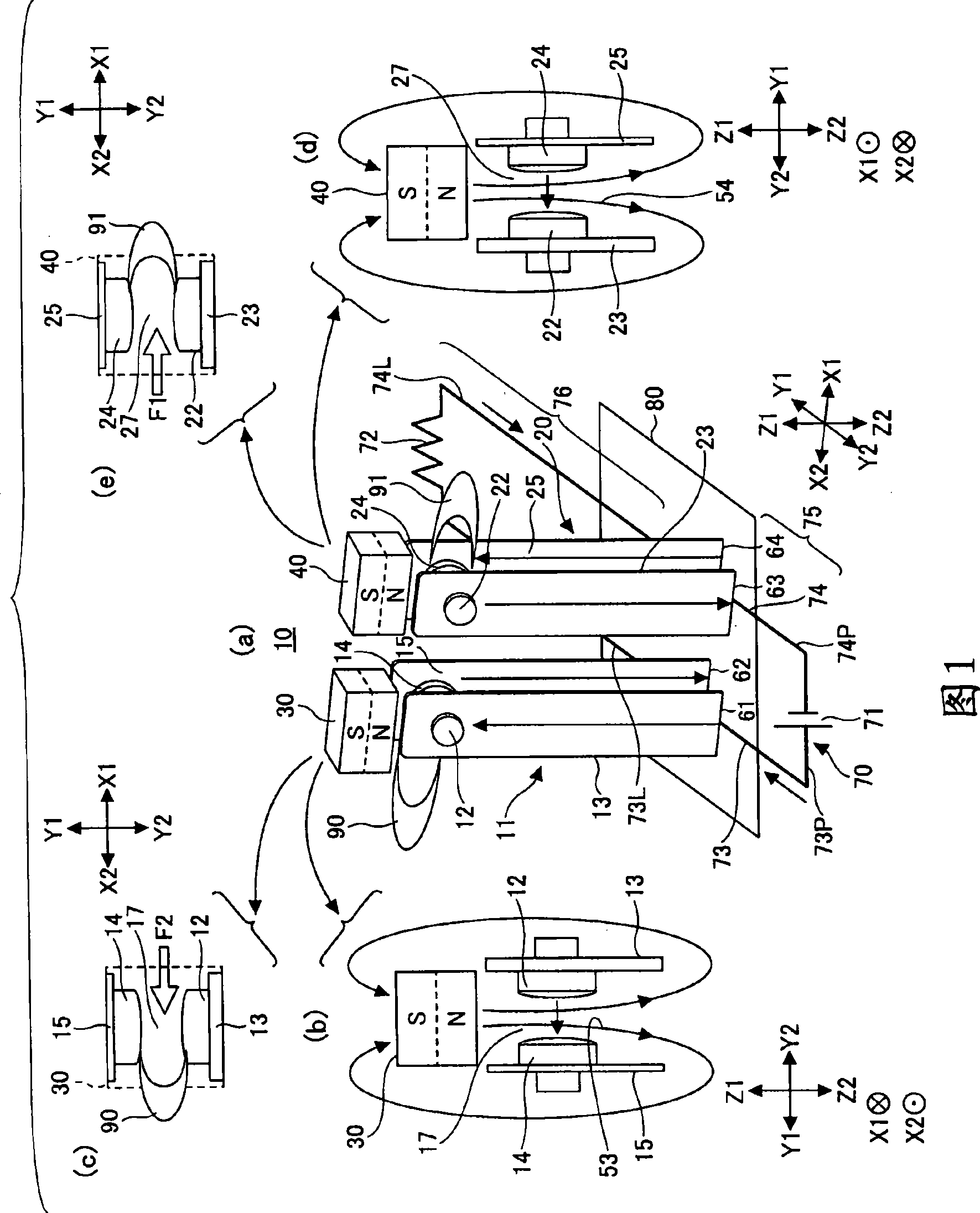
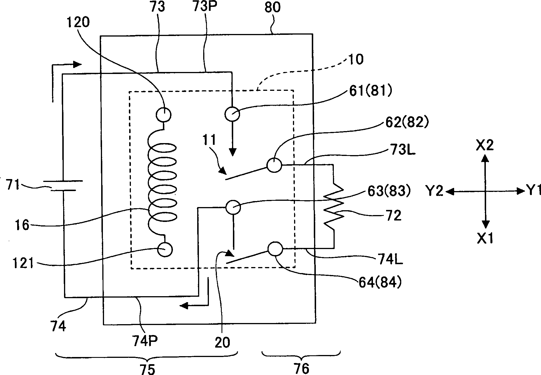
[0079] Relay 10A is an embodiment of relay 10 of the principle construction shown in FIG. 1 . The relay 10A has: a first opening and closing member 11 and a second opening and closing member 20, on the Y2 side of the base 100, the two opening and closing members are respectively located on the X2 and X1 sides; the yoke 102, which is arranged in a vertical (upright) posture At the middle of the base 100; the armature 103 and the insert...
no. 2 approach
[0108] Figure 8A to Figure 8C These are the X2 side sectional view, the Y2 side sectional view, and the bottom view (Z2 side) of the relay 10B according to the second embodiment of the present invention, respectively.
[0109] The relay 10B includes two relay bodies 130X1 and 130X2 which are integrated and arranged side by side in the X1-X2 direction of the housing 110B. The structures of the two relay bodies 130X1 and 130X2 are all the same as Figure 9 The configuration of the shown relay body 130 is the same.
[0110] The casing 110B includes a relay body receiving part 115X1 for accommodating the relay body 130X1, and the casing 110B further includes a relay body accommodating part 115X2 for accommodating the relay body 130X2. The relay body housing parts 115X1 and 115X2 are made to be arranged side by side in the X1-X2 direction. The first and second permanent magnet blocks 30 and 40 are fixed to the top plate part 111B2 of the relay body housing part 115X2 and the to...
no. 3 approach
[0118] The schematic diagram in Fig. 10 shows a relay 10D according to a third embodiment of the present invention.
[0119] FIG. 11 is a perspective view of relay 10D viewed through housing 110D.
[0120] Figure 12A 12D is a top sectional view (Z1 side), an X2 side sectional view, a Y2 side sectional view, and a bottom view (Z2 side) of the relay 10D, respectively.
[0121] Except that the first and second permanent magnet blocks 30 and 40 in the relay 10 shown in FIG. 1 are replaced by a common single permanent magnet block 45, the relay 10D of the third embodiment has the same same construction.
[0122] The permanent magnet block 45 has an elongated rectangular parallelepiped shape, and extends across the gaps 17 and 27 , with its N pole on the Z2 side and its S pole on the Z1 side. Since this configuration can apply a magnetic field of the same orientation to the gaps 17 and 27, a design using a single permanent magnet block 45 is feasible.
[0123] In actual situati...
PUM
| Property | Measurement | Unit |
|---|---|---|
| Length | aaaaa | aaaaa |
| Width | aaaaa | aaaaa |
| Thickness | aaaaa | aaaaa |
Abstract
Description
Claims
Application Information