Thin-film omni-directional wideband surface conformal antenna

A technology of conformal antennas and antennas, which is applied in the directions of antennas, resonant antennas, antenna supports/mounting devices, etc., can solve the problems of destroying the aerodynamic characteristics of the platform and the influence of the electromagnetic characteristics of the platform, and achieve improved aerodynamic characteristics and electromagnetic characteristics, and light weight , the effect of flexible structure

Active Publication Date: 2009-03-18
BEIHANG UNIV
View PDF0 Cites 9 Cited by
  • Summary
  • Abstract
  • Description
  • Claims
  • Application Information

AI Technical Summary

Problems solved by technology

[0002] At present, the omnidirectional broadband antennas used on electronic communication mobile platforms generally use saber-type antennas. Although the saber antenna has a simple structure and stable electrical performance, due to the limitation of the antenna form, the assembly of the saber antenna and the platform requires the saber antenna. It protrudes from the surface of the platform, destroying the aerodynamic characteristics of the platform, and also has a certain impact on the electromagnetic characteristics of the platform

Method used


Image

  • Thin-film omni-directional wideband surface conformal antenna
  • Thin-film omni-directional wideband surface conformal antenna
  • Thin-film omni-directional wideband surface conformal antenna

Examples


Embodiment 1

[0028] Example 1: The antenna of the present invention conforms to the surface of the cuboid object

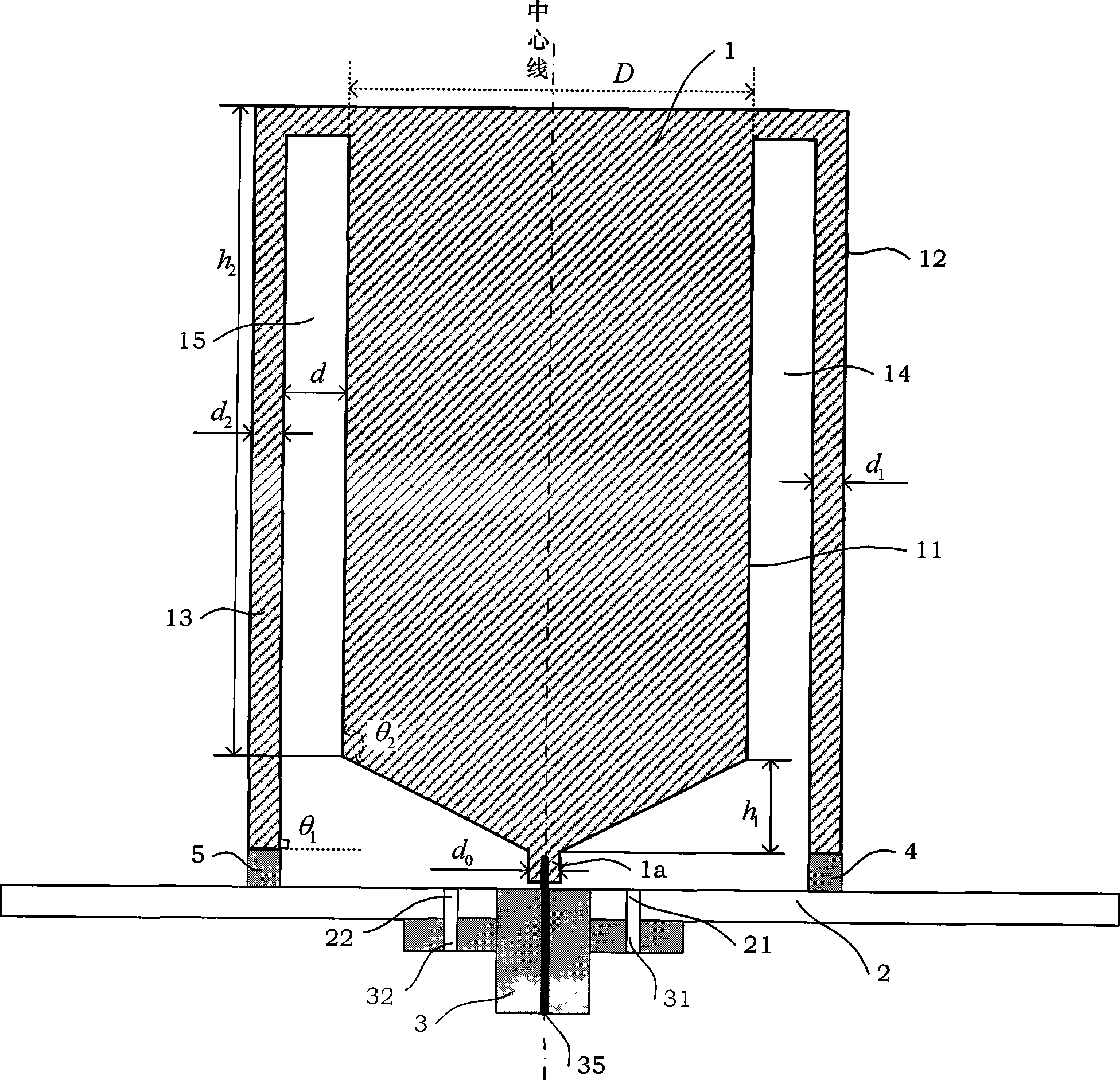
[0029] see Figure 4 As shown, there is a cuboid object on the mounting plate 2, if the antenna 1 of the present invention is installed at the junction of the cuboid object and the mounting plate 2, the center line of the antenna 1 should overlap with the vertical center line 6 of the conformal surface of the cuboid object, Then the feeding end 1a of the antenna 1 is located at the bottom center of the conformal surface of the cuboid object, and the antenna 1 is attached to the surface of the cuboid object.

[0030] When the antenna designed in the present invention conforms to the surface of the cuboid, the bending position of the antenna varies with the width of the conformal surface of the cuboid. The specific situation is:

[0031] If the width of the conformal surface of the cuboid object is less than the width D of the top, the conformal antenna is bent at a position...

Embodiment 2

[0032] Example 2: Conformity between the antenna of the present invention and the object in the shape of a parabolic cylinder

[0033] see Figure 5 As shown, there is an object in the shape of a parabolic cylinder on the mounting plate 2. If the antenna 1 of the present invention is installed at the junction of the object in the shape of the parabolic cylinder and the mounting plate 2, the center line of the antenna 1 should be consistent with the shape of the parabolic cylinder. The vertical centerline 7 of the conformal surface of the object overlaps, so the feeding end 1a of the antenna 1 is located at the bottom center of the conformal surface of the parabolic cylindrical object, and the antenna 1 is attached to the surface of the parabolic cylindrical object. The antenna 1 of the present invention is symmetrical to the vertical center line 7 of the parabolic cylindrical object, and conforms to the configuration of the parabolic cylindrical object.


PUM


Abstract

The invention discloses a slice omnidirectional broadband surface conformal antenna, which is formed by an antenna (1), a coaxial feeding joint (3), an A resistance (4) and a B resistance (5), wherein the structure of the A resistance (4) is same with the structure of the B resistance (5), the sensitive end of a probe (35) in the coaxial feeding joint (3) is welded on the feeding end (1a) of the bottom end of the antenna (1), the coaxial feeding joint (3) is mounted on the lower plate surface (2b) of a mounting plate (2), the A resistance (4) is mounted between the bottom of a right antenna wing (12) of the antenna (1) and the upper plate surface (2a) of the mounting plate (2), and the B resistance (5) is mounted between the bottom of a left antenna wing (13) of the antenna (1) and the upper plate surface (2a) of the mounting plate (2). The slice omnidirectional broadband surface conformal antenna simultaneously adopts bottom-end two-side resistance loading and a bottom-end conical gradation structures which lead the band width of the slice omnidirectional broadband surface conformal antenna to be widened. Compared with the bowed antennas which are used at present, the surface conformal antenna with a slice structure can reduce the negative influence to platform pneumatic property, the installation position is flexible, and a place which is convenient for antennas to play efficiency is chosen to mount.

Description

technical field [0001] The present invention relates to an omnidirectional broadband antenna, more particularly, refers to an omnidirectional broadband antenna with a sheet structure that can conform to the surface structure of an installation object or a conformal platform. Background technique [0002] At present, the omnidirectional broadband antennas used on electronic communication mobile platforms generally use saber antennas. Although the saber antennas are simple in structure and stable in electrical performance, due to the limitation of the antenna form, the assembly of the saber antenna and the platform requires the saber antenna to be Protruding from the surface of the platform destroys the aerodynamic characteristics of the platform, and also has a certain impact on the electromagnetic characteristics of the platform. Contents of the invention [0003] The object of the present invention is to provide an omnidirectional broadband antenna with a sheet structure ...

Claims


Application Information

Patent Timeline
Patent Type & Authority Applications(China)
IPC IPC(8): H01Q1/22H01Q1/36H01Q9/04H01Q13/08H01Q23/00
Inventor 陈爱新姜铁华苏东林王永忠魏文轩张艳君
Owner BEIHANG UNIV
Why Eureka
Try Eureka