
Cyclic ink supply method and cyclic ink supply system

A technology of ink supply and ink supply tank, which is applied in printing and other directions, can solve problems such as difficulty, increase of system space, and ink entering the air path, so as to save system cost, reduce system complexity, and ensure printing quality.

Inactive Publication Date: 2009-03-25
PEKING UNIV FOUNDER GRP CO LTD +2
View PDF0 Cites 29 Cited by
  • Summary
  • Abstract
  • Description
  • Claims
  • Application Information

AI Technical Summary

Problems solved by technology

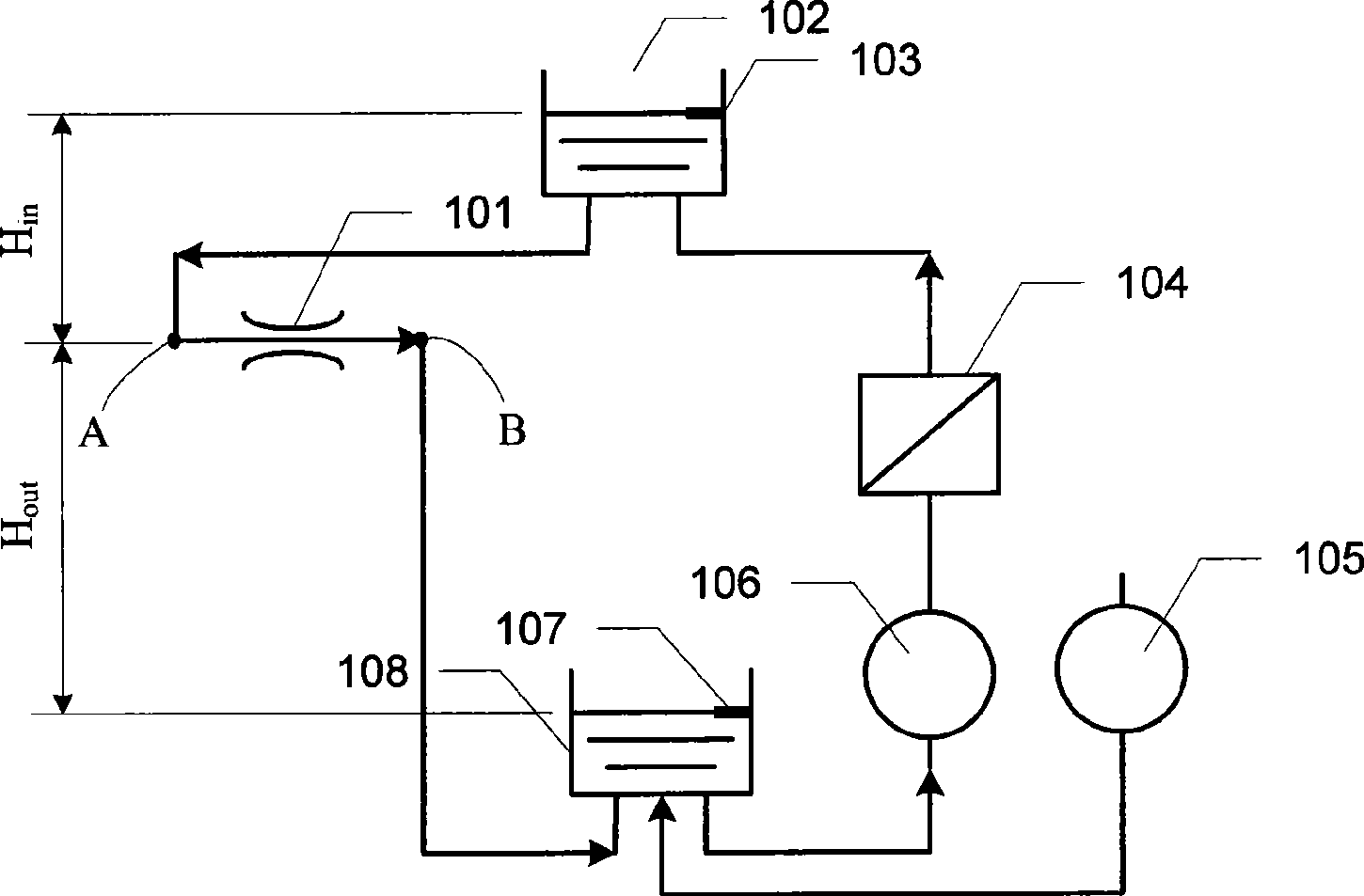
[0006] However, there are still many shortcomings in the ink supply method in the prior art. For example, in the prior art, it is difficult to generate positive pressure and negative pressure at both ends of the nozzle by dynamically controlling the height difference of the ink liquid level in the upper and bottom ink cartridges. ; and, since the negative pressure needs to be greater than the positive pressure (H out The value is larger), this gravity ink supply method also has higher requirements on the space position, which increases the space occupied by the system
[0007] The system structure of the prior art 2 is relatively compact, and the pressure control at both ends of the nozzle is also ideal, but the air path setting responsible for generating and controlling the negative pressure is too complicated and expensive, and has become a bottleneck restricting this technology; and, in When adjusting the voltage of the ink supply pump, improper handling may easily cause ink to enter the air circuit and damage the air circuit components

Method used


Image

  • Cyclic ink supply method and cyclic ink supply system
  • Cyclic ink supply method and cyclic ink supply system
  • Cyclic ink supply method and cyclic ink supply system

Examples


Embodiment Construction

[0036] In order to illustrate the technical solutions of the embodiments of the present invention more clearly, the embodiments of the present invention will be described in detail below in conjunction with the accompanying drawings. The following descriptions are only some embodiments of the present invention. For those of ordinary skill in the art, Other implementations of the present invention can also be obtained according to these embodiments without any creative effort.

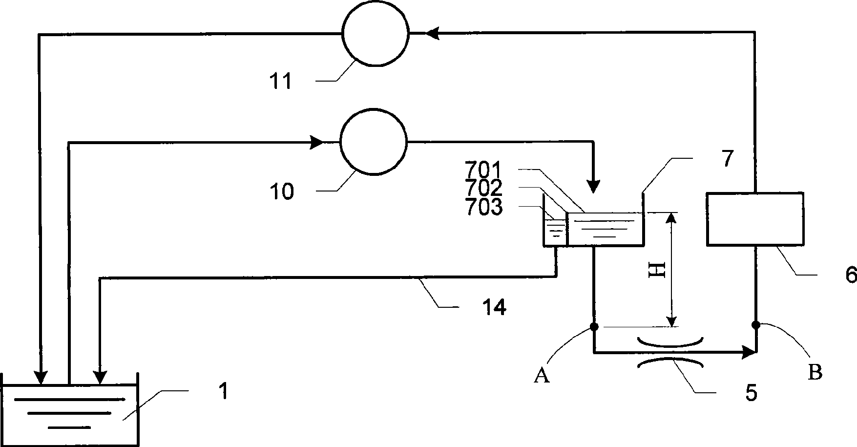
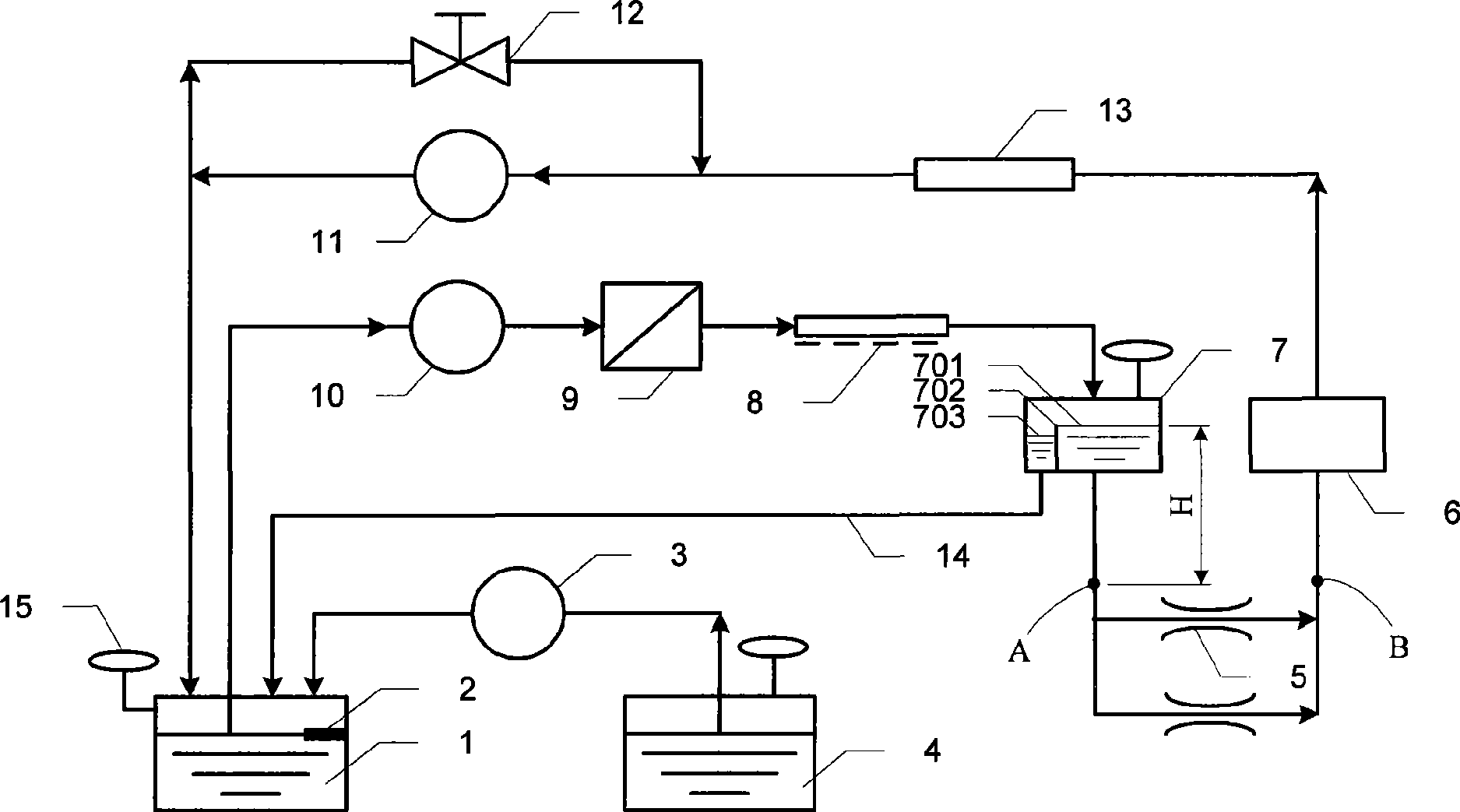
[0037] A circulating ink supply system provided by Embodiment 1 of the present invention, such as figure 2 As shown, it includes an ink cartridge 1, an ink inlet pool 7 equipped with an overflow beam 702, a discharge groove 703 and an ink supply groove 701, and an ink inlet pump 10. The ink inlet end of the ink inlet pump 10 is connected to the ink cartridge 1, The ink outlet end of the ink inlet pump 10 is connected to the inlet of the ink supply tank 701 of the ink inlet pool 7, and the outlet of the...


PUM


Abstract

The invention discloses a circulation ink supply method and a circulation ink supply system, relating to the ink supply technique. The method and the system can ensure the printing quality, simultaneously, the system complexity can be reduced and the system cost is saved. The circulation ink supply system provided by the embodiment comprises an ink box, an ink inlet pool which is provided with an overflow beam, a discharging trough and an ink supply trough, and an ink inlet pump; the ink inlet end of the ink inlet pump is connected with the ink box; the ink outlet end of the ink inlet pump is connected with the inlet of the ink supply trough of the ink supply pool; the discharging trough outlet of the ink inlet pool is connected with the ink box, wherein, the ink supply trough outlet of the ink inlet pool is connected with the nozzle inlet which is arranged below the ink supply trough of the ink inlet pool; the nozzle inlet is connected with the ink inlet end of at least one nozzle; the ink outlet end of at least a nozzle is connected with the nozzle outlet; the nozzle outlet is connected with the ink inlet end of a returning ink pump; the ink outlet end of the returning ink pump is connected with the ink box.

Description

technical field [0001] The invention relates to ink supply technology, in particular to a circulating ink supply method and a circulating ink supply system. Background technique [0002] Inkjet printers are common office equipment in the modern office field. They are generally favored by users because of their simple structure, low noise, low price, and brilliant and lifelike color printing effects. [0003] Currently, an inkjet printing head in a through-flow mode is usually used in an inkjet printer, and ink is supplied in a circular manner. This serial flow mode can not only take away the bubbles and impurities in the nozzle through the flowing ink, but also promote heat exchange and stabilize the ink temperature. [0004] Prior art one provides a kind of gravity ink supply method of serial flow, as figure 1 As shown, the vertical distance H between the liquid surface of the upper ink cartridge 102 and the inlet A of the nozzle 101 in It determines the positive pressur...

Claims


Application Information

Patent Timeline
IPC IPC(8): B41J2/175B41J2/18
Inventor 方应龙陈峰刘志红
Owner PEKING UNIV FOUNDER GRP CO LTD
Learn More