Diving type stepping filling mechanism of vertical type bottle filler

A filling machine and stepping motor technology, applied in packaging, bottle filling, liquid bottling, etc., can solve the problems of slow speed response, difficulty in precise control of downward movement, large volume, etc., and achieve precise axial movement The effect of high height and compact structure

Inactive Publication Date: 2009-03-25
JIANGSU JINWANG PACKING SCI TECH CO LTD
View PDF0 Cites 5 Cited by
  • Summary
  • Abstract
  • Description
  • Claims
  • Application Information

AI Technical Summary

Problems solved by technology

[0002] There are several filling heads on the vertical filling machine. All the filling heads must have the function of moving down to fill and then moving up to reset during the filling process. At present, the mechanism to realize this function is the motor through the speed change mechanism. After the speed is changed

Method used


Image

  • Diving type stepping filling mechanism of vertical type bottle filler

Examples


Embodiment 1

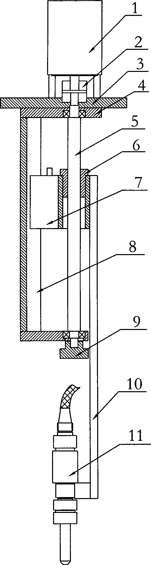
[0010] Embodiment 1: The submerged stepping filling mechanism of the vertical filling machine includes a stepping motor 1, a coupling 2, a support plate 3, a slide rail frame 4, a ball screw 5, a screw nut 6, a lifting Slider 7, slide rail 8, fine-tuning handwheel 9, connecting plate 10 and filling head 11, stepper motor 1 is fixedly installed on the upper end of support plate 3, slide rail frame 4 is fixed on the lower end of support plate 3, slide rail 8 Fixed on the slide rail frame 4, the lifting slider 7 and the slide rail 8 can be slidably moved and connected, the screw nut 6 is fixed on the lifting slider 7, the ball screw 5 is screwed in the screw nut 6, and the ball screw The two ends of 5 are installed on the slide rail frame 4 through bearings, the upper end of the ball screw 5 is directly connected with the stepping motor 1 through the coupling 2, and the lower end of the ball screw 5 is equipped with a fine-tuning hand wheel 9 and a connecting plate 10 The upper e...


PUM


Abstract

The invention discloses a submersible step racking mechanism of a vertical racking mechanism, which comprises an electric step motor, a shaft joint, a supporting board, a slide rail frame, a ball screw, a feed screw nut, an elevating slide block, a slide rail, a fine tuning hand wheel, a connecting board and a racking head, two ends of the ball screw are arranged on the slide rail frame through a bearing, the upper end of the ball screw is connected with the electric step motor directly, and the electric step motor drives the ball screw to rotate so as to drive the racking head to move upwards and downwards, thus satisfying the submerged racking action requirement of the racking head. The submersible step racking mechanism of the vertical racking mechanism is characterized in that original complex gear shift mechanisms are replaced by the electric step motor which has compact structure and high precision of axial movement.

Description

technical field [0001] The invention relates to a vertical filling machine, in particular to a lifting filling mechanism of the vertical filling machine. Background technique [0002] There are several filling heads on the vertical filling machine. All the filling heads must have the function of moving down to fill and then moving up to reset during the filling process. At present, the mechanism to realize this function is the motor through the speed change mechanism. After the speed is changed, the screw nut mechanism drives the lifting of the filling head. This type of lifting mechanism is not only complex in structure, large in size, and slow in speed response, but also difficult to accurately control the downward movement distance and difficult to adapt to modern high-precision filling requirements. Contents of the invention [0003] In order to further simplify the structure of the lifting mechanism of the filling head of the vertical filling machine and improve the l...

Claims


Application Information

Patent Timeline
IPC IPC(8): B65B3/04B67C3/26
Inventor 蒋文强沈六俊尹奋中房国荣胡桂香
Owner JIANGSU JINWANG PACKING SCI TECH CO LTD
Why Eureka
Try Eureka