Binding machine with buckling-free steel belt

A technology of strapping machine and steel belt, which is applied to the parts of strapping machinery, strapping materials, paper/cardboard containers, etc., which can solve the problems of large volume and inability to bind materials tightly, and achieve the effect of saving locks and reducing costs

Inactive Publication Date: 2011-06-08
张温堤
View PDF1 Cites 5 Cited by
  • Summary
  • Abstract
  • Description
  • Claims
  • Application Information

AI Technical Summary

Problems solved by technology

The disadvantage of this buckleless steel belt strapping machine is that the lower punch scissors are between the bundled material and the steel belt when bundling the material, and the lower punch scissors are flat and have a large volume, so when the bundling is finished, exit the bundling machine Finally, there is a gap left by the evacuation of the lower punch scissors between the steel belt and the bundled material, so the material cannot be tightly bound, and because the bottom of the lower punch scissors is flat, it is suitable for bundling into a square Stacked materials, and for materials stacked into drums, using this buckle-free steel belt strapping machine for bundling will cause the bundling and locking to be completed, and the machine cannot be taken out.

Method used


Image

  • Binding machine with buckling-free steel belt
  • Binding machine with buckling-free steel belt
  • Binding machine with buckling-free steel belt

Examples


Embodiment Construction

[0018] Embodiments of the present invention are now further described in conjunction with the accompanying drawings:

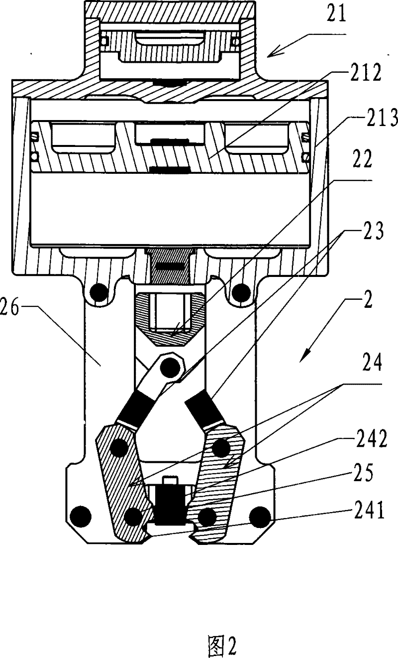
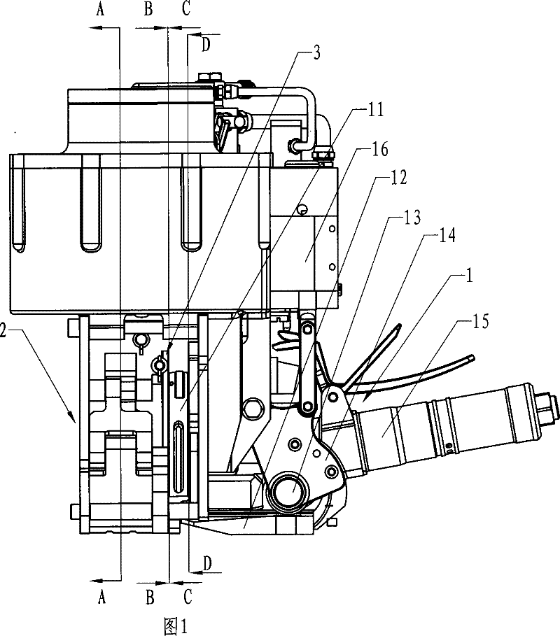
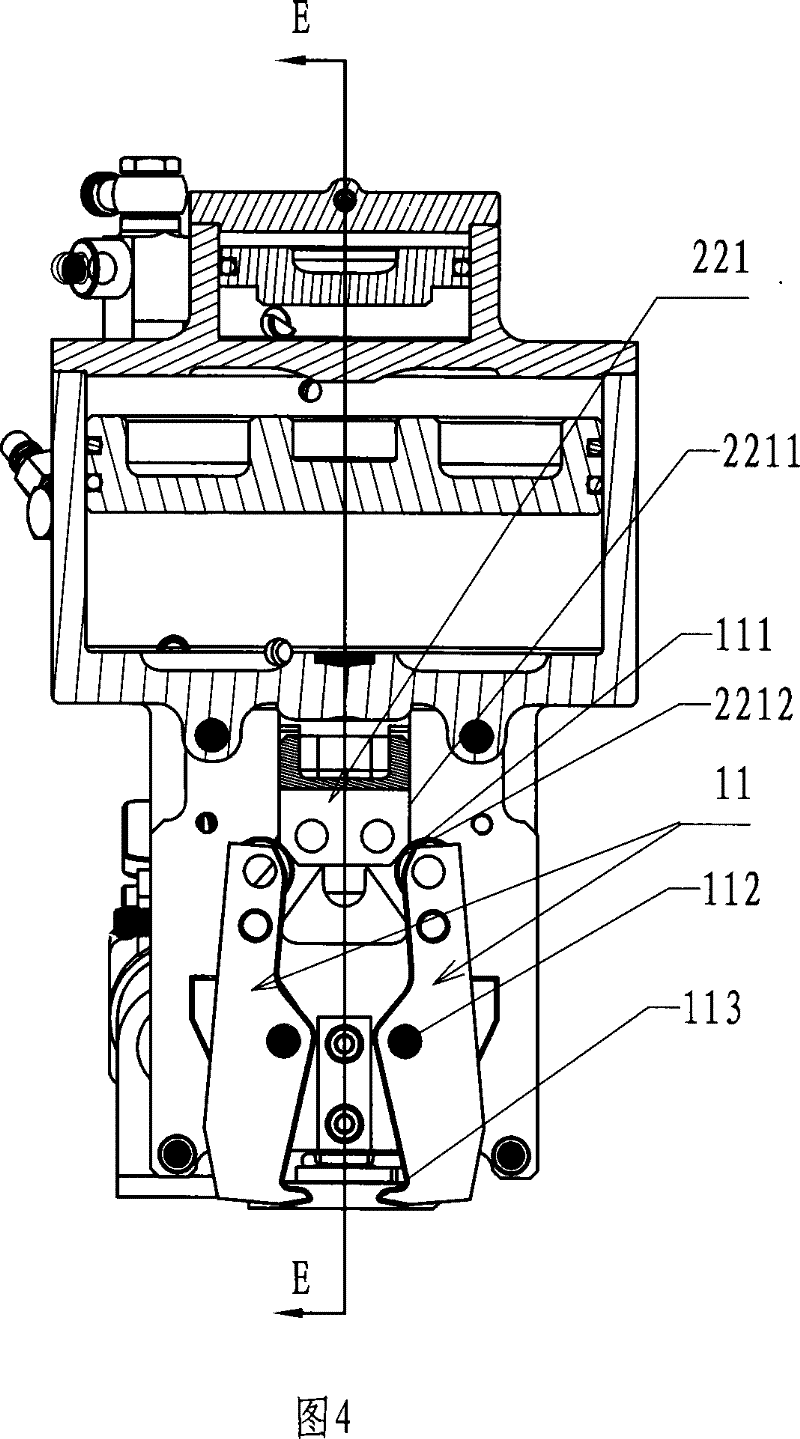
[0019] Such as figure 2 , Figure 4 , Figure 5 , Figure 6 , Figure 7 , Figure 8 , Figure 9 As shown, an embodiment of a buckle-free steel strip binding machine of the present invention includes a steel strip tensioning mechanism 1, a press-lock steel strip mechanism 2 and a steel strip cutting mechanism 3, wherein the press-lock steel strip mechanism 2 is located at the steel strip cutting In front of the mechanism 3, the steel strip cutting mechanism 3 is located in front of the steel strip tensioning mechanism 1; the steel strip tensioning mechanism 1 includes a pressing plate 11 on the front side, a tensioning base 12 on the bottom side, and a tensioning base 12 on the bottom side. The tensioning roller 13 and its mounting seat 14 on the upper rear side of the base 12 are positioned at the handle 15 on the rear side, and the handle 15 is provide...


PUM


Abstract

The invention relates to a non-fastening steel strip packing machine which comprises a steel strip tensing mechanism, a steel strip pressing and locking mechanism and a steel strip cutting mechanism. The steel strip pressing and locking mechanism comprises left and right static indentation blocks, a left dynamic indentation block and a right dynamic indentation block, a front back fixing side board and a back fixing side board that are used for fixedly connecting a second air cylinder and a second air cylinder body, and a slide block that is fixed on a telescopic rod of the second air cylinder, the lower end of the slide block is respectively hinged with left and right connecting boards, the lower ends of a left connecting board and a right connecting board are hinged with the left dynamic indentation block and the right dynamic indentation block, the lower ends of the left dynamic indentation block and the right dynamic indentation block respectively take a shape of an arc indented claw, the static indentation blocks are fixedly arranged between the left and right dynamic indentation blocks and simultaneously above the arc indented claws, the second air cylinder is a double-levelair cylinder, the slide block has an extension end, side walls at two sides of the extension end take a shape of being vertical at the upper end and inwardly-tilted at the lower end, a left pressure board and a right pressure board are hinged with a back fixing board, the lower ends of the left pressure board and the right pressure board are provided with inward dummy clubs that are arranged below a tensing seat, and the upper ends of the left pressure board and the right pressure board respectively press against the side walls of the extension end of the slide block.

Description

technical field [0001] The invention relates to a steel belt binding machine, in particular to a buckle-free steel belt binding machine. Background technique [0002] Ordinary steel belt strapping machine is to put the steel belt into the lock buckle and then tighten it, and use the lock buckle to lock the overlap of the steel belt. This kind of strapping machine needs to use the lock buckle, so it increases Especially for some large steel factories, because the amount of binding is very large, the cost of this lock is not a small fee. In view of this, buckle-free steel belt strapping machines have also appeared. This strapping machine compresses and deforms the overlapping ends of the tensioned steel belts to lock the steel belts, thereby saving the buckle. For example, the Chinese patent No. is 200520029673.6, the date of authorization announcement is January 17, 2007. What is disclosed in the patent literature titled "Steel Belt Mechanism for Binding Machine Without Lock...

Claims


Application Information

Patent Timeline
Patent Type & Authority Patents(China)
IPC IPC(8): B65B13/22B65B13/04B65B13/30
Inventor 吴世康
Owner 张温堤
Why Eureka
Try Eureka