Wave beam shaping method

A beamforming method and beamforming technology, applied in the directions of space transmit diversity, advanced technology, climate sustainability, etc., can solve the problem of antenna units working in nonlinear regions, etc.

Inactive Publication Date: 2009-03-25
CHINA ACAD OF TELECOMM TECH
View PDF0 Cites 9 Cited by
  • Summary
  • Abstract
  • Description
  • Claims
  • Application Information

AI Technical Summary

Problems solved by technology

[0017] In view of this, one of the objects of the present invention is to provide a beamforming method, which can solve the problem that in the eigenbeamforming method, when the antenna unit is fed with power exceeding its maximum transmission capability, the antenna unit will work in abnormal Technical Problems in the Linear Region

Method used


Image

  • Wave beam shaping method
  • Wave beam shaping method
  • Wave beam shaping method

Examples


Embodiment Construction
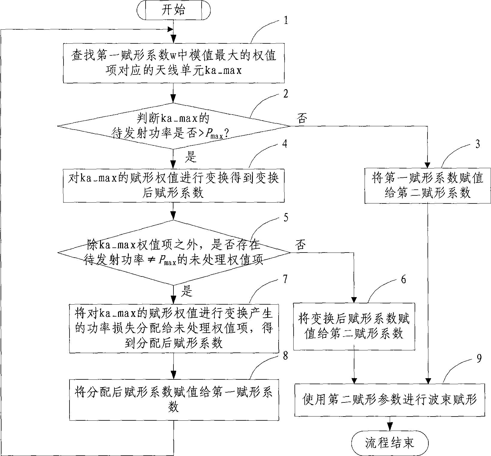
[0072] The core idea of ​​the technical solution of the present invention is: when the eigenbeamforming algorithm is applied to calculate the shaping coefficients, and when the transmission power of an antenna exceeds the maximum transmission power of the antenna unit, the shaping coefficients of the eigenbeamforming algorithm are transformed to obtain a new set of Forming coefficient, using the new forming coefficient for forming, the antenna transmission power will not exceed the maximum transmission power of the antenna, and the base station can achieve the maximum power transmission, and the forming gain has almost no loss or a lot of loss compared with the eigenbeam forming algorithm Less, so as to still maintain the advantages of relatively fixed beamforming.

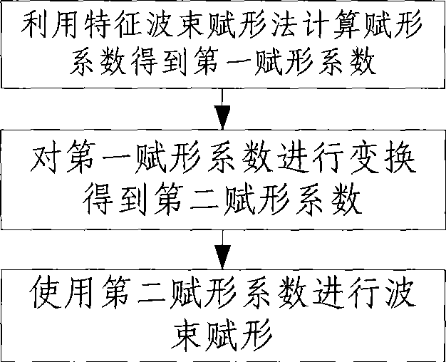
[0073] Such as figure 1 Shown, basic realization step of the present invention is as follows:

[0074] Step 1. Calculate the beamforming coefficient according to the characteristic beamforming algorithm, and set ...


PUM


Abstract

The invention relates to the beam forming technical field in a mobile communication system, and particularly relates to a beam forming method which combines the advantages of both a characterized beam forming method and a fixed beam forming method and a device thereof. The invention has the advantages of reallocating the power loss which is beyond the maximum emissive power of an antenna unit through the method of switching the result acquired by the characterized beam forming method, and better solving the problem that the maximum emissive power of the characterized beam forming method can not reach the maximum emissive power of an antenna array.

Description

technical field [0001] The present invention relates to the technical field of beamforming in a mobile communication system, in particular to a method and device for optimizing a characteristic beamforming method. Background technique [0002] Since the 1990s, beamforming technology has been widely used in mobile communication systems, and array antennas using beamforming technology are generally called smart antennas. The smart antenna uses beamforming to direct the main beam to the desired user for transmission and reception, increasing the power of the receiving end. The smart antenna can also adjust the weighting coefficients of each antenna unit to align the null of the array antenna pattern with the interfering user according to the spatial characteristics of the interfering signal, which can reduce the signal power from (directed to) the interfering user. At the edge of the cell, since the beamforming improves the receiving power of the receiving end, the range cover...

Claims


Application Information

Patent Timeline
Patent Type & Authority Applications(China)
IPC IPC(8): H04B7/04H04L1/02
CPCY02D30/70
Inventor 吴柯维孙长果徐红艳
Owner CHINA ACAD OF TELECOMM TECH
Why Eureka
Try Eureka