Trigger type sprayer

A sprayer and trigger technology, applied in the direction of spraying devices, liquid spraying devices, single handheld devices, etc., can solve problems such as injuries and children's unsafety

Active Publication Date: 2009-03-25
APOLLO IND
View PDF0 Cites 0 Cited by
  • Summary
  • Abstract
  • Description
  • Claims
  • Application Information

AI Technical Summary

Problems solved by technology

When the container of the sprayer contains a hazardous liquid and these children can easily pull the trigger, the sprayed liquid can cause injury to them
That said, traditional trigger spray devices have the disadvantage of being unsafe for children

Method used


Image

  • Trigger type sprayer
  • Trigger type sprayer
  • Trigger type sprayer

Examples


Embodiment Construction

[0043] Now, preferred embodiments of the present invention will be described in detail with reference to the accompanying drawings.

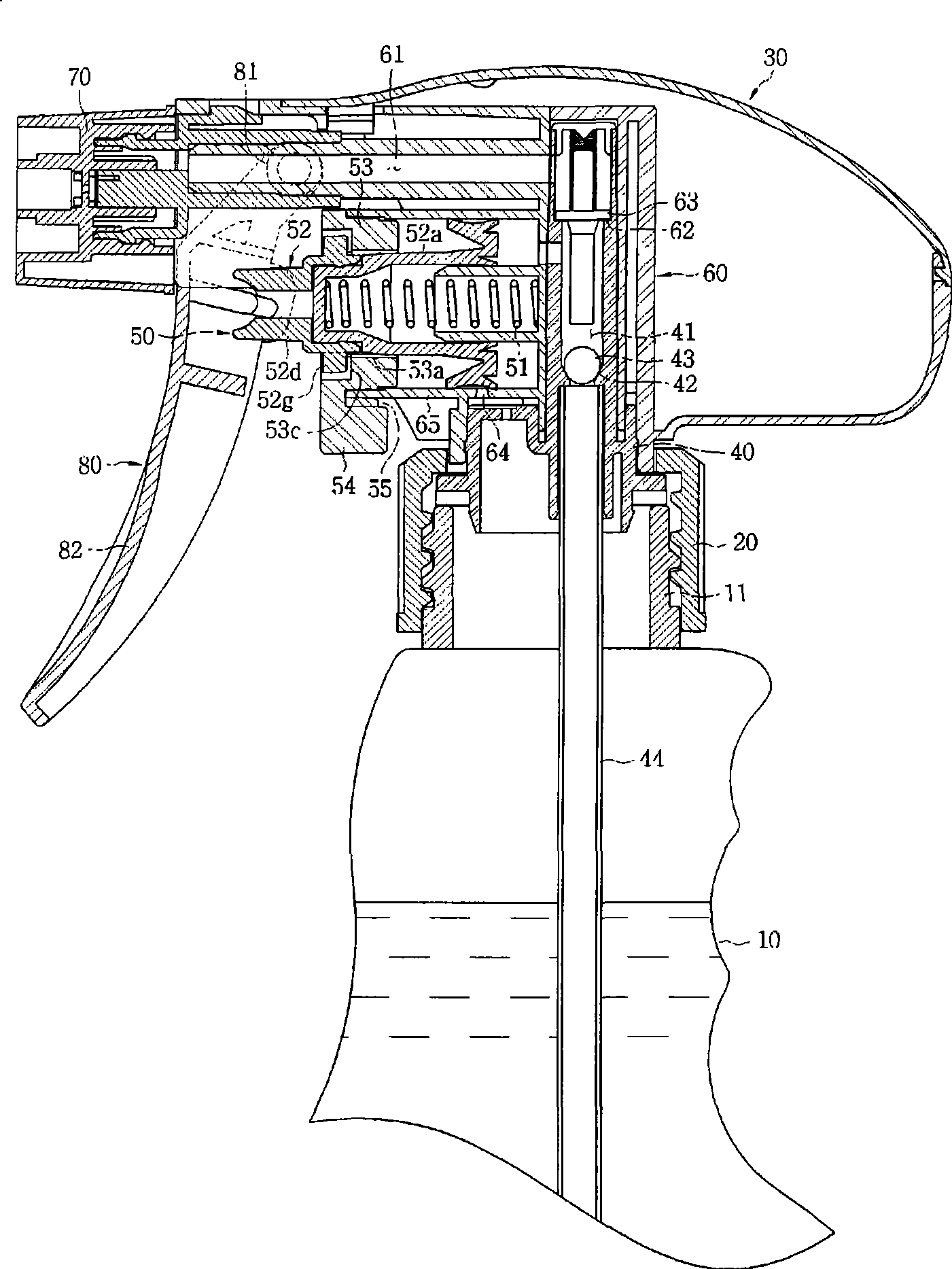
[0044] figure 1 is a sectional view showing a trigger injector device according to the present invention.

[0045] Such as figure 1 As shown, the small injector adopting the concept of the present invention comprises: a container 10 for storing a liquid substance; a cover 20 detachably coupled to the upper part of the container 10; an injector device 30 mounted on the cover 20 for pumping Suction and ejection of liquid substances.

[0046] The container 10 is made of synthetic resin to accommodate liquid substances. The container 10 includes a neck 11 having a certain inner diameter and integrally formed at an upper portion of the container 10 . The neck 11 is externally threaded on the outer surface to be combined with the cap 20 .

[0047] The cap 20 detachably couples the injector device 30 to the neck 11 of the container 10 . The cover...


PUM


Abstract

A trigger sprayer device is disclosed, which is configured in such a way that the trigger and plunger are operable only after unlocking, to be childproof. The trigger sprayer device includes: a plunger unit (52) that is placed to reciprocate inside the cylinder (65) and elastically supported by a restoring spring (51), in which the front end of the plunger unit (52) is associated with a rear side of the trigger (80) and the sides of the plunger unit (52) protrudently forms locking ribs; and a locking member (53) that is pivotally fitted in an opened end of the cylinder (65), and has a through hole (53a), shaped as a ring, to allow the front end of the plunger unit (52) to be past through, forming slide grooves (53b) on the inner circumference of the through hole (53a) to se not lectively allow the locking ribs (52g) to be moved. Therefore, when the slide grooves (53b) and the locking ribs (52g) are not parallel with each other, the trigger (80) and the plunger unit (52) maintain their locking state. Thus, the operation of the trigger (80) can be restricted. Ac not cordingly, the trigger sprayer device is childproof. In addition, since the plunger unit (52) has always been received in the through-hole (53a), the plunger unit (52) is not deformed although the trigger is pressed from both its sides and impacted while the sprayer is carried.

Description

technical field [0001] The present invention relates to a small sprayer and, more particularly, to a trigger sprayer device that draws and sprays liquid as the plunger reciprocates and holds the plunger in a locked condition. Background technique [0002] Typically, a small injector sucks and ejects the substance contained within its container. For this purpose, the injector mounts the injector device in the upper part of the container. That is, a conventional small sprayer includes: a container for storing liquid or paste cosmetics or other substances; a cap detachably coupled to the neck of the container; Suctions and ejects a specific unit of liquid on each trigger. [0003] A conventional trigger sprayer device is configured to include: a main body mounted on the upper portion of the cover, having a nozzle at its front end; a suction unit having a plunger placed in the main body for sucking and pumping the liquid in the container; a trigger, pivotally coupled to the f...

Claims


Application Information

Patent Timeline
IPC IPC(8): B05B9/03
CPCB05B11/3059B05B11/3011B05B11/1011B05B11/1059B05B11/0037
Inventor 李镕大
Owner APOLLO IND
Why Eureka
Try Eureka