Guide-rail brake with electro-magnetic activation

A technology of brakes and guide rails, used in elevators, transportation and packaging, etc., can solve the problem of not necessarily giving all the braking force, and achieve the effect of short air gap, simple structure, and small distribution range of operation delay.

Inactive Publication Date: 2009-03-25
KONE CORP
View PDF2 Cites 9 Cited by
  • Summary
  • Abstract
  • Description
  • Claims
  • Application Information

AI Technical Summary

Problems solved by technology

Another problem is that existing rail brakes do not necessarily give full braking force when released, because residual magnetism causes counterforce

Method used


Image

  • Guide-rail brake with electro-magnetic activation
  • Guide-rail brake with electro-magnetic activation
  • Guide-rail brake with electro-magnetic activation

Examples


Embodiment Construction

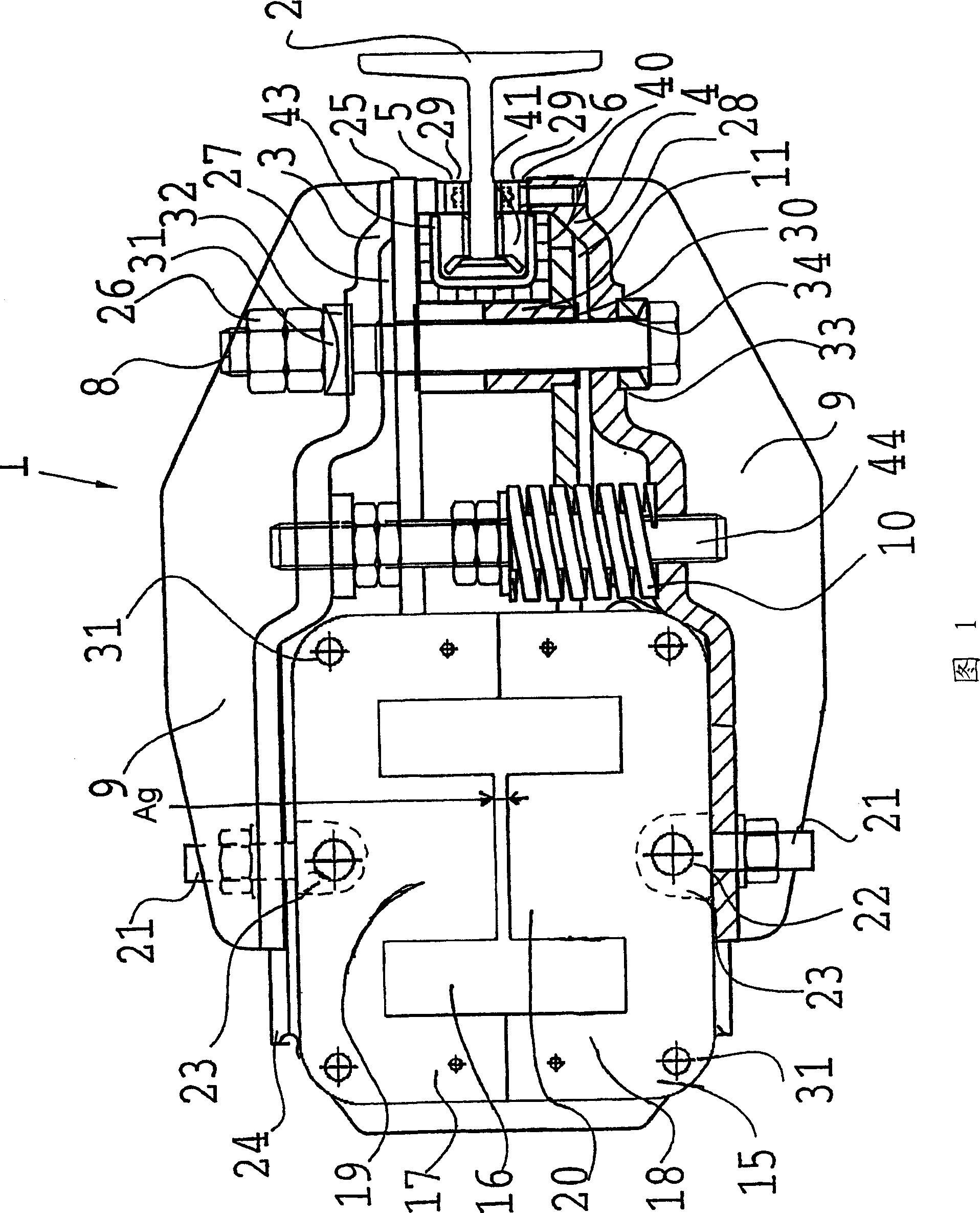
[0023] Figure 1 shows a top view of a guide rail brake that can be used in the present invention. In FIG. 1 , the guide rail 2 can be seen between the brake pads 5 , 6 fastened to the jaws 3 , 4 of the brake clip. The jaws 3 , 4 are hinged to one another by means of screws 7 , 8 . For the sake of clarity, the bolts 7 are not shown in FIG. 7 . Jaws 3,4 are stiffened by ribs 9. The spring 10 acts on the jaws, pushing the jaws 3, 4 further apart from each other, in which case the brake pads 5, 6 are pressed against the guide rail 2 because the jaws are hinged to the brake pads by means of the bolts 7, 8. 5, 6 and the spring 10, so that the jaw plates cannot move away from each other at the position of the bolt. The spring 10 is guided by a central pin 44 .

[0024] The rail brake 1 is opened and held open by means of a power part 15, preferably a magnet, which enables a controllable movement. The control of magnets or other actuating means can take place by command of the el...


PUM


Abstract

A guide-rail brake (1) of an elevator and method for controlling the brake, which brake comprises a frame part fixed to the elevator car, and a prong part, which contains turning jaws (3,4) that correspond to the guide rail (2) via the braking surfaces when braking, a spring (10) loading the prong part to press the braking surfaces to the guide rail, a controllable mover, which is an electromagnet (15) , which electromagnet (15) contains two pulling core pieces (17,18) , the force effect of which electromagnet (15) on the prong part is opposed to the spring. In the guide-rail brake an air gap(ag) is structurally arranged between the center parts (19,20) of the pulling core pieces (17, 18) of the electromagnet of the guide-rail brake when the brake is fully energized, and a damping circuit is arranged in the coil (16) of the electromagnet (15) of the guide-rail brake to speed up operation of the guide-rail brake.

Description

technical field [0001] The invention relates to a guide rail brake as defined in the preamble of claim 1 and to a control method for a guide rail brake as defined in the preamble of claim 11 . Background technique [0002] A clip-on guide rail brake that grips the guide rail, in which the pressure on the braking surface acting on the guide rail is achieved by means of spring force, is a widely used braking device. This type of braking device is often a safety mechanism that stops the upward or downward motion of the elevator if the speed becomes too high or for some other reason. In practice, placing the brake on the elevator car, especially when adding a brake to an existing elevator, is problematic in terms of space utilization, since the brake must be quite large due to the high forces acting on it. Clip-on brakes can also be the operating brake of the elevator. Clip-operated brakes have been used, for example, in linear motor elevators. Recently, these types of brakes...

Claims


Application Information

Patent Timeline
Patent Type & Authority Applications(China)
IPC IPC(8): B66B5/18
CPCB66B5/18
Inventor 蒂莫·赛尔曼汤米·托蒂拉
Owner KONE CORP
Why Eureka
Try Eureka