
Linear compressor or refrigerating unit comprising a discharge device for fluid condensate

A technology for linear compressors and discharge devices, which is applied in liquid variable capacity machinery, mechanical equipment, machines/engines, etc., and can solve the problems of expensive surface coating and reduced performance.

Inactive Publication Date: 2009-03-25
BSH BOSCH & SIEMENS HAUSGERAETE GMBH
View PDF3 Cites 3 Cited by
  • Summary
  • Abstract
  • Description
  • Claims
  • Application Information

AI Technical Summary

Problems solved by technology

However, this surface coating is relatively expensive
[0007] A suitable thermal bridge between the pressure side of the linear compressor and the gas pressure bearing can be used to prevent ongoing condensation, but this can degrade performance during the start-up phase

Method used


Image

  • Linear compressor or refrigerating unit comprising a discharge device for fluid condensate
  • Linear compressor or refrigerating unit comprising a discharge device for fluid condensate

Examples


Embodiment Construction

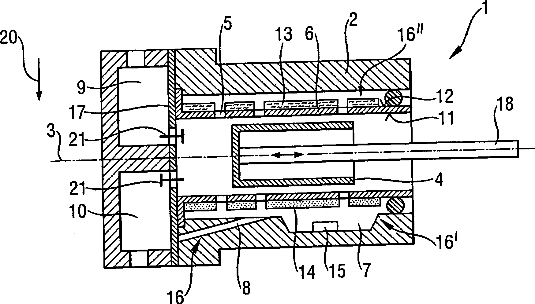
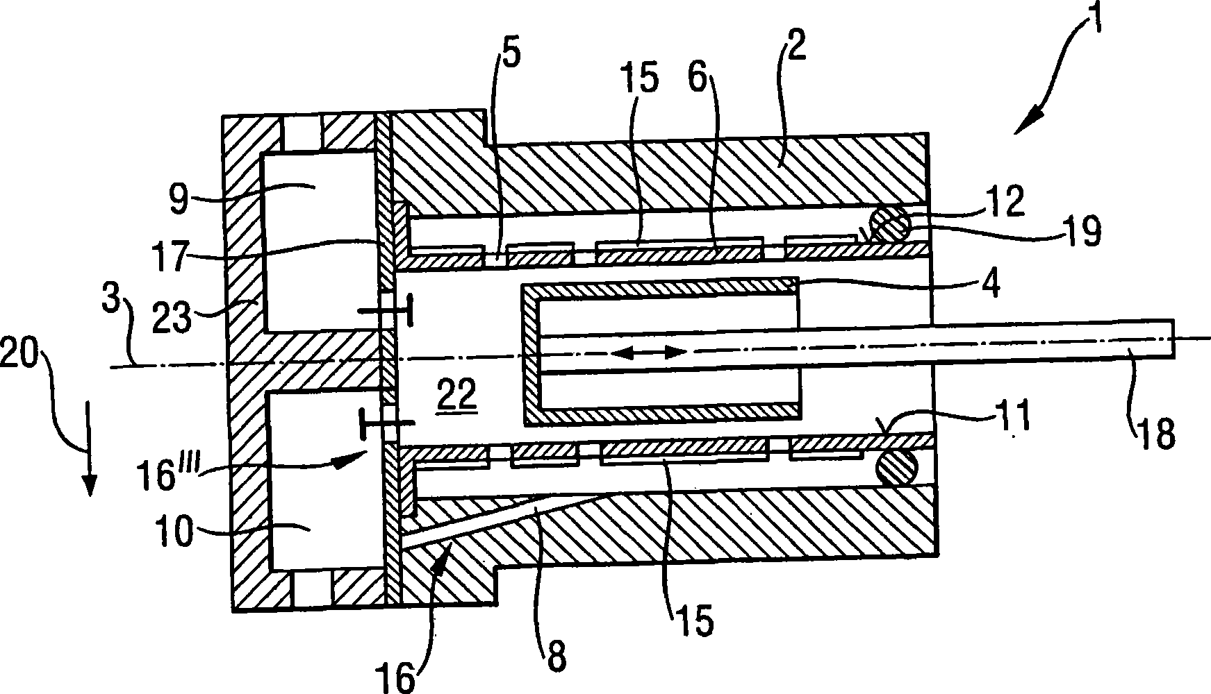
[0034] figure 1 A first embodiment of a linear compressor 1 with a piston housing 2 is shown in longitudinal section, wherein the compressor piston 4 is moved back and forth along the axis 3 by means of a piston rod 18 . The compressor piston 4 is supported by means of a housing wall 6 which has an opening 5 through which a fluid flows so that an air cushion is created between the housing wall 6 and the compressor piston 4 . Through the continuous flow of gas through the opening 5 , the compressor piston 4 is guided in a contactless manner in the housing wall 6 , which is formed as a cylinder liner. The linear compressor 1 has a suction connection 9 and a pressure connection 10 which are switched on and off in a suitable phase sequence by means of a valve plate 17 . The piston housing 2 has a recess 7 which acts as a drain 16' for fluid condensate. Any fluid condensate that forms flows from the housing wall 6 configured as a cylinder jacket into the recess 7 and collects the...


PUM


Abstract

The linear compressor (1) according to the invention or the refrigerating unit according to the invention comprising this linear compressor (1) comprises a piston housing (2) and a compressor piston (4) movable in a reciprocating manner therein along an axis (3), wherein the compressor piston (4) is mounted in the piston housing (2) by means of a housing wall (6) having openings (5) and a gaseous fluid flowing through the openings (5), wherein a discharge device (16, 16', 16', 16'') for fluid condensate is provided and is distinguished by a long service life and an especially high efficiency.

Description

technical field [0001] The present invention relates to a linear compressor or refrigeration unit comprising a piston housing, and a compressor piston movable back and forth along an axis therein, wherein the compressor piston is mounted by means of the housing wall In the piston housing, the housing wall has openings through which the gaseous fluid flows. Background technique [0002] In oil-free linear compressors, the compressor piston is separated from the housing wall by an air cushion of gaseous refrigerant that flows into the compressor piston through tiny openings through the housing wall of the piston housing. In order to maintain said gas pressure support provided by the gas cushion, a continuous inflow of gas is required, otherwise contact would be created between the compressor piston and the housing wall, causing friction and thus being subject to wear. It is known to form air cushions by means of a number of microscopic holes in the cylinder wall. US6575716 p...

Claims


Application Information

Patent Timeline
Patent Type & Authority Applications(China)
IPC IPC(8): F04B35/04
CPCF04B35/045
Inventor T·库斯尼克J-G·舒伯特M·贾基
Owner BSH BOSCH & SIEMENS HAUSGERAETE GMBH
Learn More