System for and method of edge welding using projections

A prominent, marginal technology applied in the field of resistance welding systems to reduce energy consumption and improve maneuverability

Inactive Publication Date: 2009-04-01
GM GLOBAL TECH OPERATIONS LLC
View PDF0 Cites 7 Cited by
  • Summary
  • Abstract
  • Description
  • Claims
  • Application Information

AI Technical Summary

Problems solved by technology

The invention is also used to facilitate edge welding with minimal to no edge distortion

Method used


Image

  • System for and method of edge welding using projections
  • System for and method of edge welding using projections
  • System for and method of edge welding using projections

Examples


Embodiment Construction

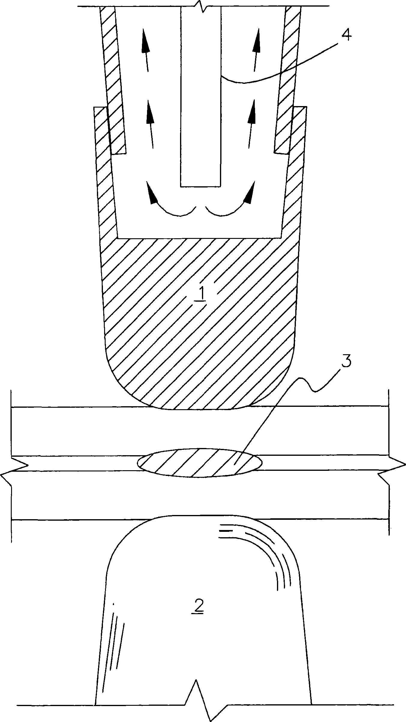
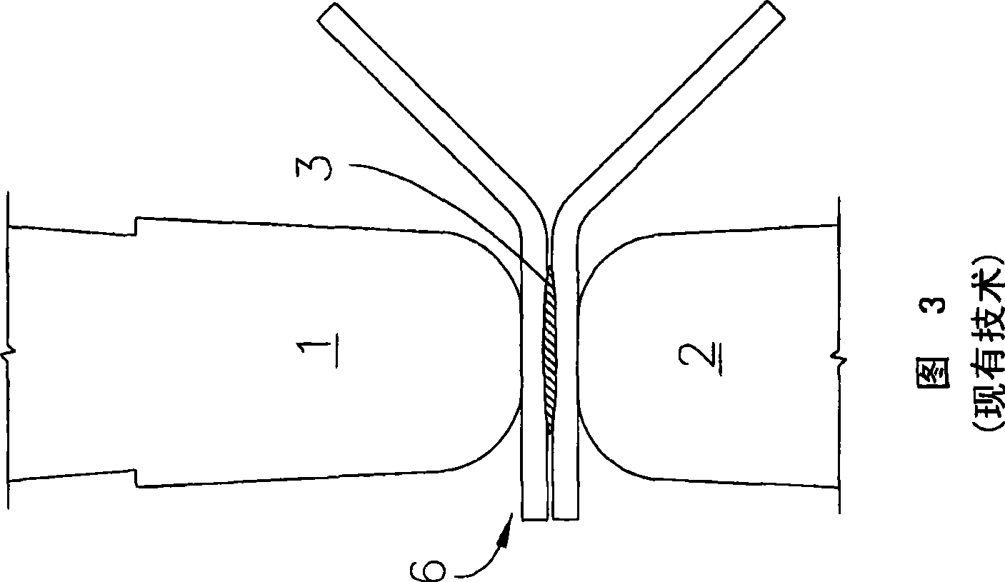
[0034] The present invention relates to a resistance welding system 10 (FIG. 4) for welding multiple (i.e., two or more) adjacent workpieces, such as automotive sheet metal or engine mount parts, to produce spot or seam welds 12 ( Figure 5 and Figure 8). Multiple sets of two workpieces 14, 16 having the same thickness are shown in the various embodiments described and illustrated herein; however, the system 10 may be used to weld a greater number of structural components having variable thickness. The workpieces 14, 16 may be formed from a wide range of rigid solid conductive metals, including steel. exist Figure 5 to Figure 5 c and Figure 7 to Figure 1 In the application shown in 1, the sheet metal workpieces 14, 16 preferably have opposing major surfaces 14a and 16a that can be joined by a two-electrode resistance / protrusion welding device such as the device 18 shown in FIG. 4 .

[0035] A novel aspect of the present invention involves the treatment of one of the workp...


PUM

PropertyMeasurementUnit
widthaaaaaaaaaa
lengthaaaaaaaaaa

Abstract

A method of edge welding a plurality of workpieces particularly useful for minimizing edge deformation and reducing the electrode size, flange size, welding force and current load necessary to produce a given weld, including the steps of forming at least one distending projection along the edge of a first workpiece, securing the projection against a second workpiece and applying a force and current load to the projection so as to fuse a portion of the projection, and a system for performing the method, including a dedicated projection forming fixture, a resistance welding apparatus preferablyhaving specialized electrodes and a controller communicatively coupled to the fixture and apparatus.

Description

technical field [0001] The present invention relates to resistance welding of multiple workpieces, and more particularly to an improved resistance welding system that utilizes edge protrusion to reduce the electrode size, flange width, welding force and current load necessary to produce the weld. Background technique [0002] Resistance welding (eg, conventional crimp spot or seam welding) systems are commonly used to join workpieces or parts in factories such as automobile manufacturing and construction. Typically, after the workpiece has been fixed in the desired configuration, at least one and more usually not two electrodes as in figure 1 , Figures 2 and 3 show the joined workpieces. The electrodes function to deliver continuous force and current through the workpieces until the electrical resistance of the workpieces generates sufficient thermal energy to create a molten weld pool between the workpieces. [0003] To avoid deforming the workpiece, the applied force and...

Claims


Application Information

Patent Timeline
Patent Type & Authority Applications(China)
IPC IPC(8): B23K11/11B23K11/36
CPCB23K11/14B23K11/115B23K11/11
Inventor A·D·哈克哈列夫S·M·沙D·C·赫钦森M·D·雷吉克C·J·布鲁吉曼
Owner GM GLOBAL TECH OPERATIONS LLC
Why Eureka
Try Eureka