
Automatic power generation and storage electric motor car

A technology of electric storage electric vehicles and self-generation, which is applied in the direction of electric vehicles, electric traction, vehicle energy storage, etc., can solve the problems of driving performance degradation of driving wheels, loss of kinetic energy of wind energy driven wheels, and increase of cruising range of electric vehicles, etc. Driving performance, the effect of realizing the driving function

Inactive Publication Date: 2009-04-01
郭树阳
View PDF0 Cites 5 Cited by
  • Summary
  • Abstract
  • Description
  • Claims
  • Application Information

AI Technical Summary

Problems solved by technology

However, during the driving process of the electric vehicle, the generated wind energy and the kinetic energy of the driven wheel have been completely lost. When the electric vehicle encounters special conditions such as heavy load and a large slope, the driving performance of the driving wheel will be significantly reduced, seriously Sometimes it will even burn the motor or the controller, causing trouble to the user
Due to the limitation of the chemical properties of the battery and the physical properties of the motor, the electrical system of electric vehicles on the market is basically a simple form of conversion from electric energy to kinetic energy, which causes a serious loss of wind energy and kinetic energy of the driven wheel. The mileage of a single charge of a car and the improvement of various driving performances of electric vehicles have brought great restrictions

Method used


Image

  • Automatic power generation and storage electric motor car
  • Automatic power generation and storage electric motor car
  • Automatic power generation and storage electric motor car

Examples


Embodiment Construction

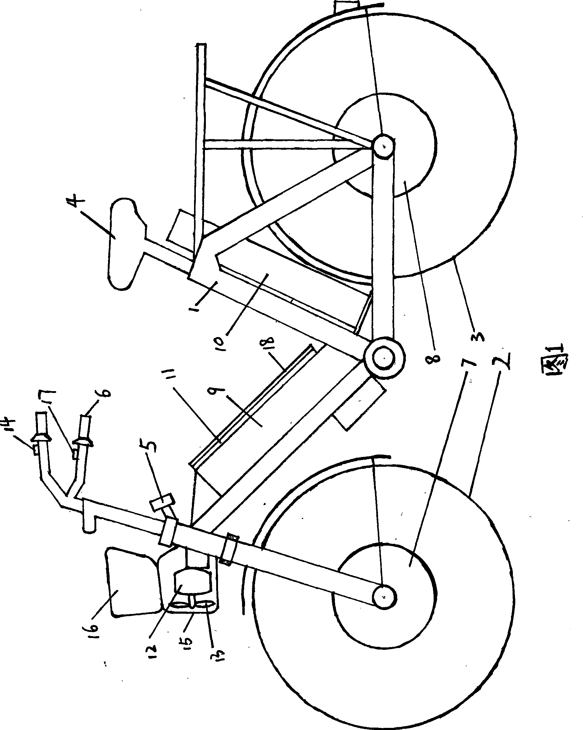
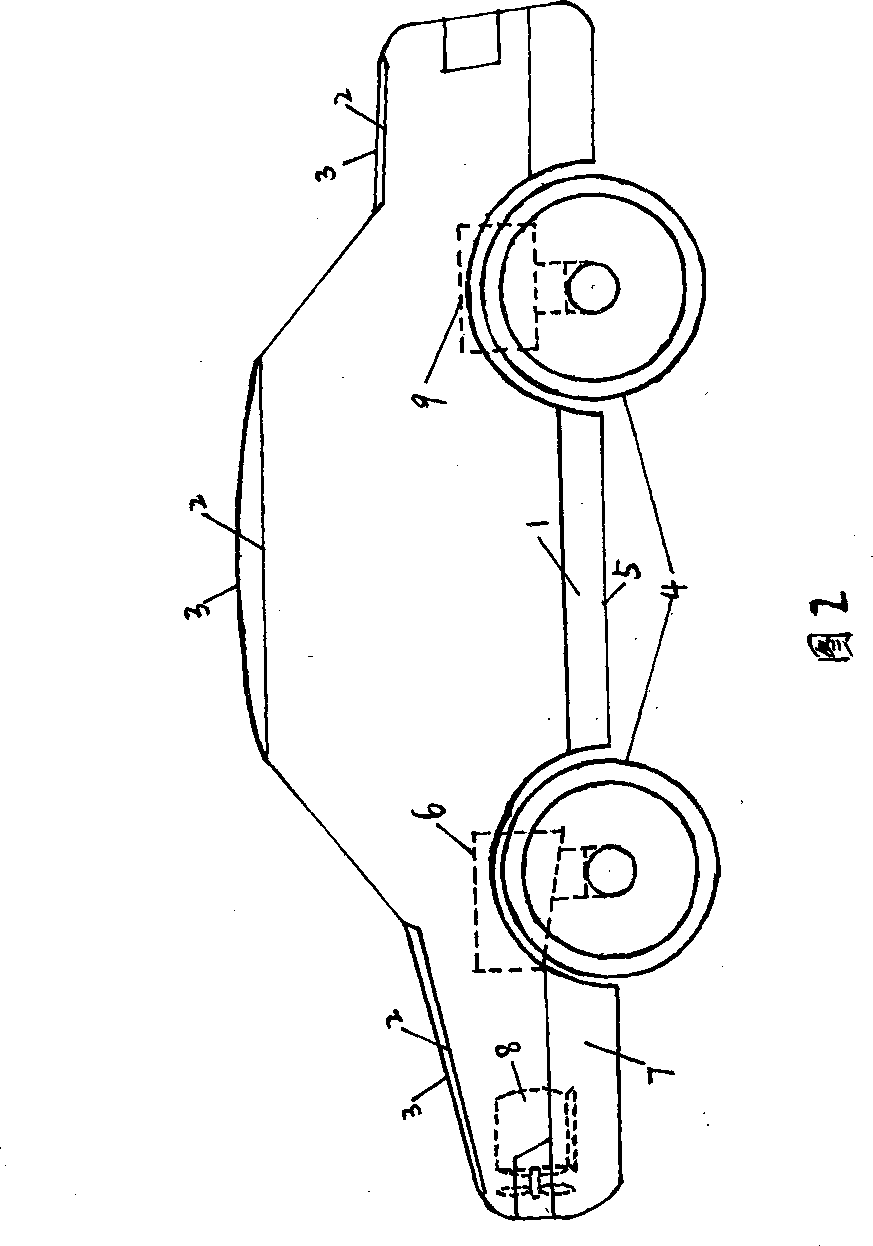
[0014] Take the two-wheel electric vehicle as an example, as shown in Figure 1, the present invention mainly consists of vehicle frame 1, front wheel 2, rear wheel 3, seat cushion 4, double pole double throw control switch 5, faucet 6, drive motor one 7, Drive motor 2 8, battery 1 9, battery 2 10, solar panel 11, transparent protective layer 18, wind generator 12, fan blade 13, wind generator shield 15, vehicle basket 16, governor 14, 17 . On vehicle frame 1, connect front wheel 2 and rear wheel 3 respectively, on the axle of front wheel 2, connect drive motor one 7, on the axle of rear wheel 3, connect drive motor two 8. Connect wind generator 12 on vehicle frame 1, connect blade 13 on the shaft of wind generator 12, the outside of wind generator 12 connects wind generator shroud 15, the top of wind generator shroud 15 connects vehicle basket 16. Battery one 9 and battery two 10 are respectively connected on the vehicle frame 1, the solar battery panel 11 is connected on the...


PUM


Abstract

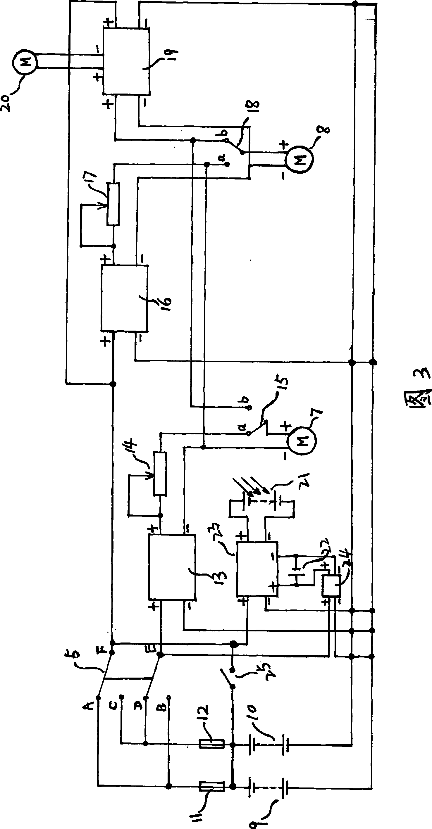
The invention discloses a self-power-generation and self-power-storage electric vehicle, which relates to a two-wheel, three-wheel or four-wheel electric vehicle technique field. The electric vehicle of the invention comprises two sets of driving motors, two sets of storage batteries and a charge controller, a wind driven generator, a solar panel and a solar charge controller, wherein, at least one set of driving circuit can be formed by selecting the combination of different switches to realize discharging of the storage battery and working of the driving motor, so that basic functions of the electric vehicle that a front wheel or a rear wheel actively moves forward, or the two wheels are driven at the same time can be achieved. In addition, two sets of charging circuit can be formed, wherein, one set is used for converting dynamic energy into electric energy by adopting a driven wheel motor and converting wind energy into electric energy by adopting the wind generator and then the electric energy is stored into the storage battery which is connected with the charge controller by the charge controller, so that the self-power-generation can be achieved; and the other set is used for converting sun light energy into electric energy by adopting the solar panel and then the electric energy is stored into the storage battery which is connected with the solar charge controller by the solar charge controller.

Description

technical field [0001] The invention relates to the technical field of two-wheel, three-wheel and four-wheel electric vehicles. [0002] Electric vehicle electrical systems for drive and energy recovery, especially electric vehicles that can realize two-wheel drive and charge while driving. Background technique [0003] At present, the electrical system of electric vehicles on the market is mainly formed by a series of batteries, control switches, controllers, governors, and electric wheels. The driving of electric vehicles depends on the one-way conversion of electric energy to kinetic energy. By manually closing the switch and adjusting the speed governor, the electric energy of the battery makes the electric wheel rotate through the switch, the controller and the speed governor, and drives the driven wheel to rotate through the frame to achieve the purpose of driving the car body. However, during the driving process of the electric vehicle, the generated wind energy and ...

Claims


Application Information

Patent Timeline
IPC IPC(8): B60L11/18B60L8/00
CPCY02T10/7083Y02T10/7005Y02T10/70Y02T10/7072
Inventor 郭树阳
Owner 郭树阳
Learn More