Assembling method of rotary double cylinder compressor pump body

A technology of a double-cylinder compressor and an assembly method, which is applied in the field of compressors, can solve the problems of small inclination distance, affecting the cooling capacity and quality of the compressor, and large range of flange self-positioning, so as to reduce leakage and improve refrigeration. amount of effect

Active Publication Date: 2009-04-01
GREE ELECTRIC APPLIANCES INC OF ZHUHAI +1
View PDF1 Cites 19 Cited by
  • Summary
  • Abstract
  • Description
  • Claims
  • Application Information

AI Technical Summary

Problems solved by technology

[0011] 1. In step B, when adjusting the position of components M and N, if the relative position of the inner diameter of the upper and lower cylinders is measured before assembling M and N as the basis for adjustment, it is cumbersome to carry out precise measurement on the assembly line, and the measurement process is Very slow, not suitable for mass production
Another assembly method is to rotate the crankshaft to adjust M and N, but it is very unrealistic to let the heavy component N self-position on the component M, that is to say, the relative position of the upper/lower cylinder is arbitrary
In this way, it is difficult to ensure that the fixed position can ensure the minimum clearance of the cylinder on the side of the compression chamber.
Therefore, there is no guarantee that the refrigerant will leak the least during the compression process, which will affect the cooling capacity and quality of the compressor
[0012] 2. In st

Method used


Image

  • Assembling method of rotary double cylinder compressor pump body
  • Assembling method of rotary double cylinder compressor pump body
  • Assembling method of rotary double cylinder compressor pump body

Examples


Example Embodiment

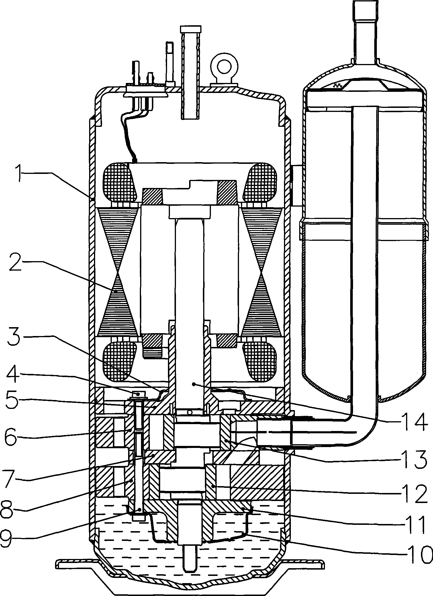
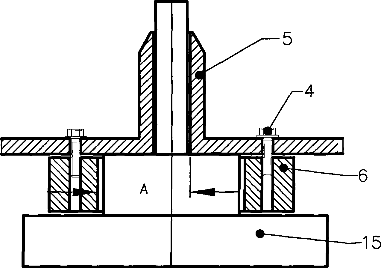
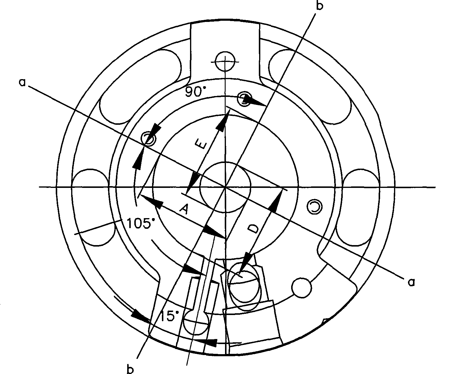
[0037] Before the actual assembly, the necessary reference data for assembly must first be obtained through measurement. Such as Figure 5 As shown, including measuring the maximum distance Amax between the upper roller 13 placed on the eccentric circle of the crankshaft 14 and the largest outer circular orbit of the crankshaft long axis, the maximum distance between the lower roller 12 placed on the eccentric circle of the crankshaft 14 and the long axis of the crankshaft The maximum distance Bmax between the outer circular tracks and the maximum distance Cmax between the lower roller 13 placed on the eccentric circle of the crankshaft 14 and the maximum outer circular track of the short shaft of the crankshaft. During the measurement, hold down the long shaft of the crankshaft by hand, make the long shaft of the crankshaft fully contact the measuring bracket, and then rotate the crankshaft to find the largest Amax, Bmax and Cmax. When the long and short shaft diameters are the sa...


PUM


Abstract

The invention discloses a method for assembling a pump body of a rotary duplex cylinder compressor, which comprises the steps: (1) after the centers of an upper cylinder and an upper flange are regulated, the upper cylinder and the upper flange are fixed into a component (M) with a short screw; (2) the center of a lower cylinder is regulated corresponding to the component (M), and the upper cylinder is separated from the component (M) after the corresponding position of the lower cylinder to the component (M); (3) after the centers of the lower cylinder and a lower flange are regulated, the lower cylinder and the lower flange are fixed into a component (N) with a short screw; (4) an upper roller, a lower roller, a sliding vane and a crank shaft are put in the component (M) and the component (N); a baffle is put between the component (M) and the component (N); according to step (2), the corresponding position of the lower cylinder to the component (M) is recorded; the component (M) is matched with the component (N) and fixed together with the component by long screws to form a whole pump body. The method can reduce spillage to the highest extent, maximizes the universal use of existing devices and has detectable clearance.

Description

technical field [0001] The invention relates to a compressor used in an air conditioner, a cold storage, etc., in particular to a double-cylinder rotary compressor. Background technique [0002] Such as figure 1 As shown, the existing two-cylinder rotary compressor generally includes: a casing 1, a motor 2 and a pump body mechanism, and the pump body mechanism mainly includes an upper muffler 3, a short screw 4, an upper flange 5, an upper cylinder 6, a middle Partition plate 7, lower cylinder 8, long screw 9, lower muffler 10, lower flange 11, lower roller 12, upper roller 13 and crankshaft 14, and upper and lower slide plates. Wherein the partition plate 7 divides the upper and lower cylinders into two independent working chambers. The upper cylinder 6 and the lower cylinder 8 are equipped with rollers and slides, and the upper and lower slides are in close contact with the upper and lower rollers under the action of the spring, so that the working chamber of each cylind...

Claims


Application Information

Patent Timeline
IPC IPC(8): F04C18/356F04C29/00F25B1/04
Inventor 黎法运李建宾陈迪松刘益民
Owner GREE ELECTRIC APPLIANCES INC OF ZHUHAI
Why Eureka
Try Eureka