Electric network peak transmission test device

A conduction test and power grid technology, applied in measurement devices, connecting devices, circuits, etc., can solve problems such as inability to accurately capture power grid spikes, and achieve the effects of reducing time-domain waveform distortion, avoiding saturation, and having a simple structure.

Inactive Publication Date: 2009-04-01
中国人民解放军海军电磁兼容研究检测中心 +1
View PDF0 Cites 4 Cited by
  • Summary
  • Abstract
  • Description
  • Claims
  • Application Information

AI Technical Summary

Problems solved by technology

[0004] In order to overcome the deficiency that the existing power grid peak conduction measurement device cannot accurately capture the power grid peak signal equivalent to the grid power supply amplitude, the purpose of the present invention is to provide a power grid peak conduction test device, which is based on the application of filter design principles , can effectively remove the influence of grid power signal on grid peak signal measurement, and make grid peak conduction signal measurement accurate and reliable

Method used


Image

  • Electric network peak transmission test device
  • Electric network peak transmission test device

Examples


Embodiment Construction

[0011] Preferred embodiments of the present invention will be described below in conjunction with the accompanying drawings.

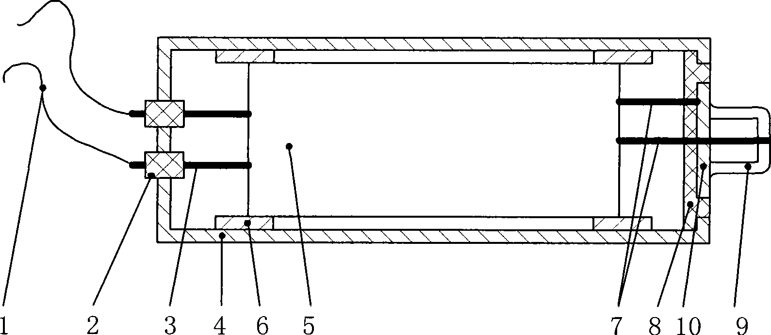
[0012] figure 1 It is a preferred embodiment of the present invention, a cross-sectional structural diagram of a grid spike conduction testing device,

[0013] Such as figure 1 As shown in the embodiment, the device of the present invention includes: power grid connection line 1, shielding insulation terminal 2, coupling network inlet line 3, metal shielding cavity 4, coupling network shielding cavity 5, cavity metal fastening strap 6 , Coupling network outlet line 7, insulating filling material 8, output terminal 9 of the measuring device, metal base 10 of the output terminal. Its configuration connection relationship is as follows:

[0014] A coupling network shielding cavity 5 is installed in the metal shielding cavity 4, and the grid connection line 1 is connected to the coupling network circuit in the coupling network shielding cavity 5 through...


PUM


Abstract

The invention discloses a device for testing the conduction of electric network peak. The device comprises a metal screen cavity (4) which is internally provided with a coupling network screen cavity (5); a network connecting wire (1) is connected with the coupling network circuit in the coupling network screen cavity (5) by an arrival line (3) of the coupling network; the electric network signal processed by the coupling network is connected with the outlet terminal (9) of the testing device by an outlet line (7) of the coupling network. The invention solves the problem that the amplitude of network source equivalent to the electric network peak signal can not be accurately detected in the prior art and has the effect of simple structure, high measuring accuracy and convenient use, etc.

Description

technical field [0001] The invention relates to a device for testing a grid peak signal, in particular to a grid peak conduction testing device capable of removing the grid fundamental wave and its low-order harmonic interference. Background technique [0002] At present, in the electromagnetic compatibility test, there is no dedicated measurement device for grid peak conduction measurement. Generally, an oscilloscope is used for direct measurement, and the grid spike is captured according to the adjustment of the trigger level of the oscilloscope. Due to the influence of the power fundamental wave and its harmonics in the power grid, it is difficult to accurately capture the peak signal of the power grid that is not much different from the fundamental wave or harmonic amplitude, which brings great difficulties to the peak conduction measurement of the power grid and easily leads to inaccurate measurement. resulting in misjudgment. [0003] Among related filter products at ...

Claims


Application Information

Patent Timeline
Patent Type & Authority Applications(China)
IPC IPC(8): G01R31/00G01R29/08H01P5/12
Inventor 汤仕平陈冰曹兵万海军王征
Owner 中国人民解放军海军电磁兼容研究检测中心
Why Eureka
Try Eureka