Method and device for expanding internal integrate circuit bus

An internal integrated circuit and bus technology, applied in the direction of electrical digital data processing, instruments, etc., can solve the problems of receiver data sampling error, communication error, slow transition edge, etc., and achieve the effect of reducing the expansion cost

Active Publication Date: 2009-04-01
BEIJING XINWANG RUIJIE NETWORK TECH CO LTD
View PDF2 Cites 14 Cited by
  • Summary
  • Abstract
  • Description
  • Claims
  • Application Information

AI Technical Summary

Problems solved by technology

[0010] Extending I with Logic Devices 2 The disadvantage of the C bus is that: due to the I 2 The serial clock line of the C interface is connected to the same clock line pin of the logic device, and the pin of each device has a certain capacitive impedance (generally around 10pF), when there are many slave devices (more than 8 ), on the one hand, the capacitive load of the clock signal line will increase to a larger value, because the capacitive load can prevent the level jump, which will prevent the level from sending a fast jump, when the signal level is from 0 to 1 jump, the jump edge (rising edge) will become very slow; on the other hand, when the number of devices increases, when the signal level jumps, multiple slave devices will simultaneously reflect the jump signal multiple times, and the original The slowly rising signal pulls back to a lower level
This signal distortion (Distortion) may make the receiver data sampling error, because there is a back groove on the clock edge, the receiver may misjudge two rising clock edges, and the slave device samples data on the rising edge of the clock , so the slave device oversamples the data, causing the I 2 C communication error, resulting in unpredictable consequences

Method used


Image

  • Method and device for expanding internal integrate circuit bus
  • Method and device for expanding internal integrate circuit bus
  • Method and device for expanding internal integrate circuit bus

Examples


Embodiment Construction

[0032] Figure 6 The flow chart of the embodiment of the method for extending the internal integrated circuit bus of the present invention includes:

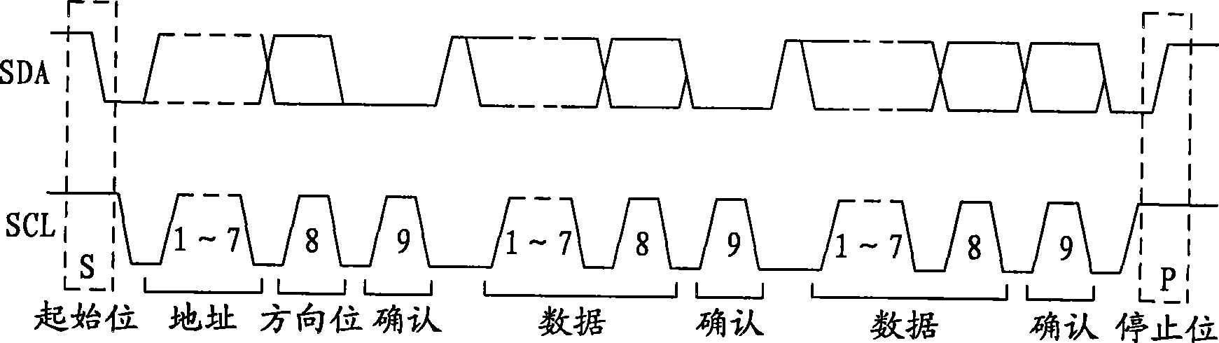
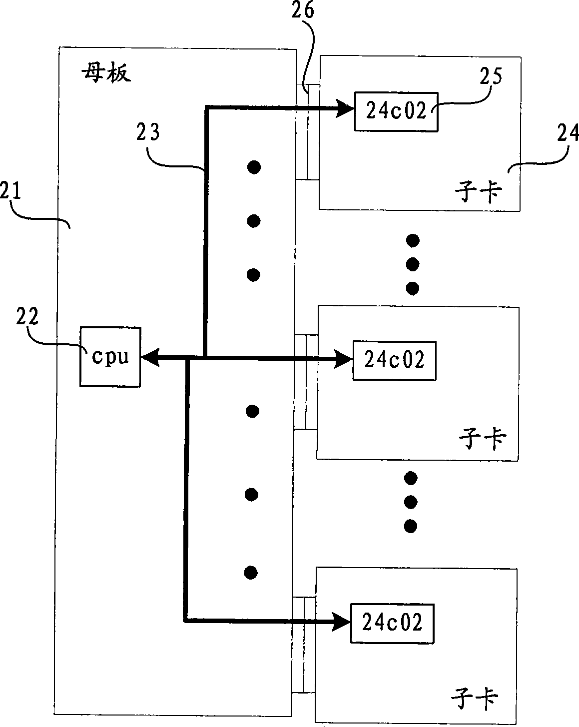
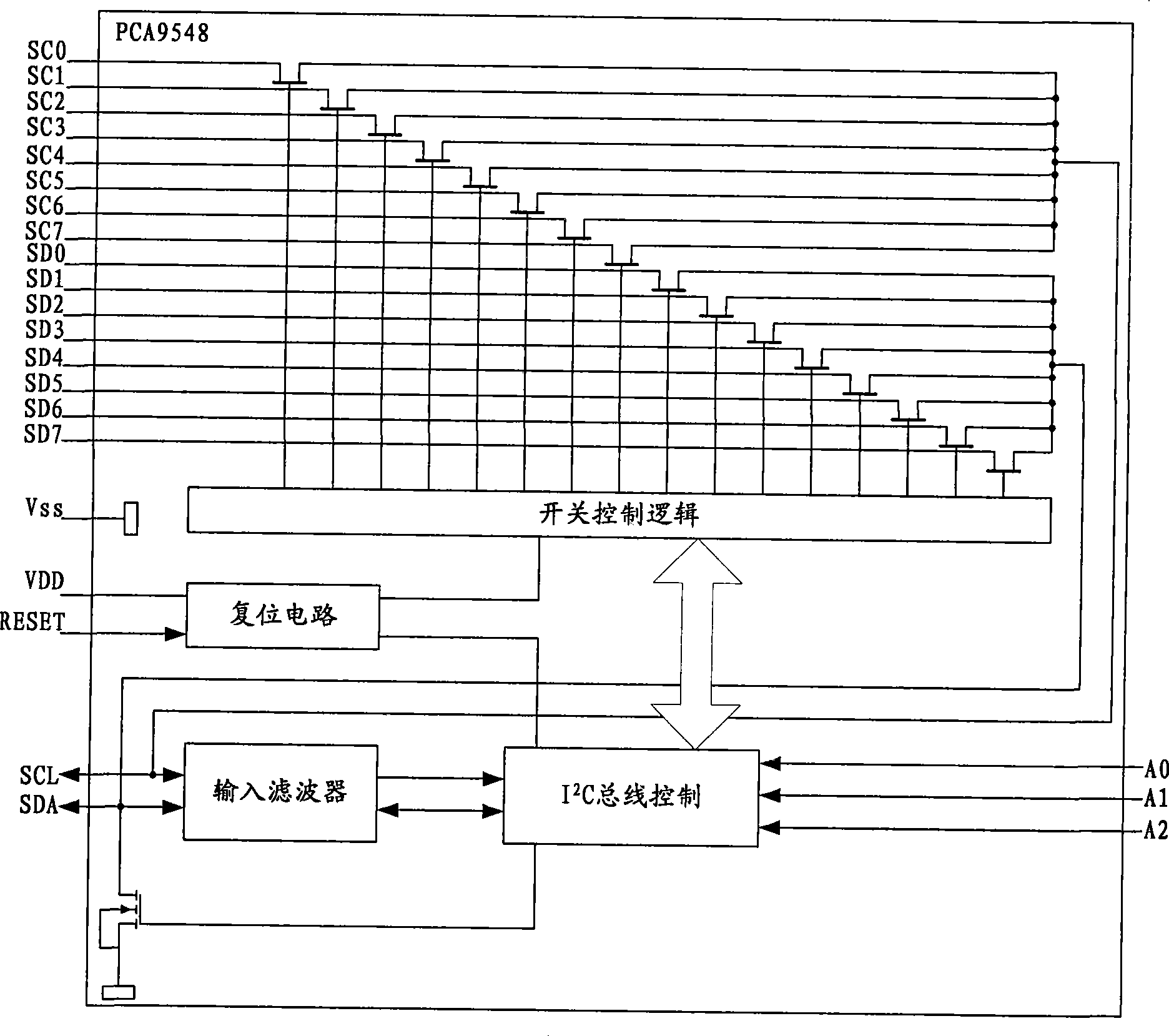
[0033] Step 61, pass the I 2 The serial clock line (SCL) of the C-bus is expanded into multiple serial clock lines; a strobe multiplexer can 2 The serial clock line of the C bus is extended to multiple I 2 The serial clock line of the C bus; when there are multiple I 2 C bus can be used with I 2 The same number of strobe multiplexers for the C bus, one-to-one correspondence, to expand each I 2 SCL of the C bus. The gating multiplexer can control the gating of the SCL before and after the expansion by the programmable input / output (PIO) interface signal of the controller, see the description in the second embodiment of the device for details.

[0034] Step 62, connecting the plurality of serial clock lines to each slave device; wherein, each slave device is to be connected to I 2 C-bus devices.

[0035] Step 63, the I 2 ...


PUM


Abstract

The invention relates to a method and a device used for extending internal integrated circuit bus; wherein, the method comprises the steps as follows: the serial clock wire of the internal integrated circuit I<2>C bus is extended as a plurality of serial clock wires by a strobe multiplexer; a plurality of serial clock wires are connected with all slave devices; the serial data wires of the I<2>C are directly connected with all slave devices; the device comprises a strobe multiplexer which is connected with a controller by a PIO wire and a serial clock wire of the I<2>C bus; the strobe multiplexer is connected with all slave devices by the extended serial clock wires; the controller is directly connected with all slave devices by the serial data wires of the I<2>C. the extension of I<2>C bus in a modularization design system is achieved by a simple logic device strobe multiplexer, usage of an expensive programmable I<2>C extension device is avoided, the extension cost of the I<2>C bus and the cost of the modularization design system are greatly reduced, and the method and the device are suitable for environments where the cost is strictly controlled.

Description

technical field [0001] The present invention relates to the technical field of electronic system application design, in particular to an extended internal integrated circuit (Inter-Integrated Circuit, I 2 C) bus method and device. Background technique [0002] Bus (Bus) refers to a group of transmission lines that transmit information from one or more source components to one or more destination components by time-division multiplexing. According to the way of transmitting data, it can be divided into serial bus and parallel bus. In a serial bus, binary data is sent to the destination device bit by bit through a data line; in a parallel bus, there are usually more than 2 data lines. [0003] I 2 The C bus is a simple bidirectional two-wire serial bus developed by Philips for effective control between microelectronic devices or components. each connected to the I 2 The devices of the C bus can be set by the unique address set by the hardware and the simple host / slave rel...

Claims


Application Information

Patent Timeline
Patent Type & Authority Applications(China)
IPC IPC(8): G06F13/40
Inventor 黄金灿
Owner BEIJING XINWANG RUIJIE NETWORK TECH CO LTD
Why Eureka
Try Eureka