Electrode unit and ionizer

An ion generator and electrode unit technology, applied in electrical components, static electricity, circuits, etc., can solve the problems of difficulty in increasing the spraying speed and low spraying ability, and achieve the effects of preventing recombination, improving the ability to remove static electricity, and increasing the spraying speed.

Inactive Publication Date: 2009-04-01
HUGLE ELECTRONICS
View PDF4 Cites 8 Cited by
  • Summary
  • Abstract
  • Description
  • Claims
  • Application Information

AI Technical Summary

Problems solved by technology

In the electrode needle unit 12 shown in FIG. 6 of Patent Document 2, although the opening 415 is large, the ejection ability is not high.
In addition, in the electrode assembly 40 shown in FIG. 6 of Patent Document 1, although the discharge port 48a is narrowed to increase the injection velocity, there is clean air compressed in the wide passage because the clean air flows from the narrow passage to the wide passage. Swelling, the problem of difficulty in increasing the injection speed

Method used


Image

  • Electrode unit and ionizer
  • Electrode unit and ionizer
  • Electrode unit and ionizer

Examples


Embodiment Construction

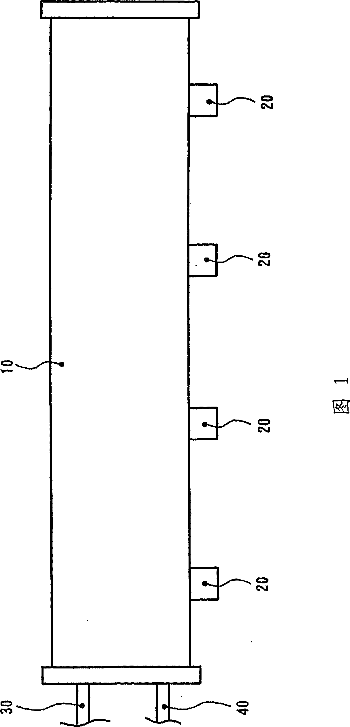
[0036] Hereinafter, an electrode unit and an ion generator according to an embodiment of the present invention will be described with reference to the drawings. In this embodiment, a pulsed AC type ion generator will be described as an example.

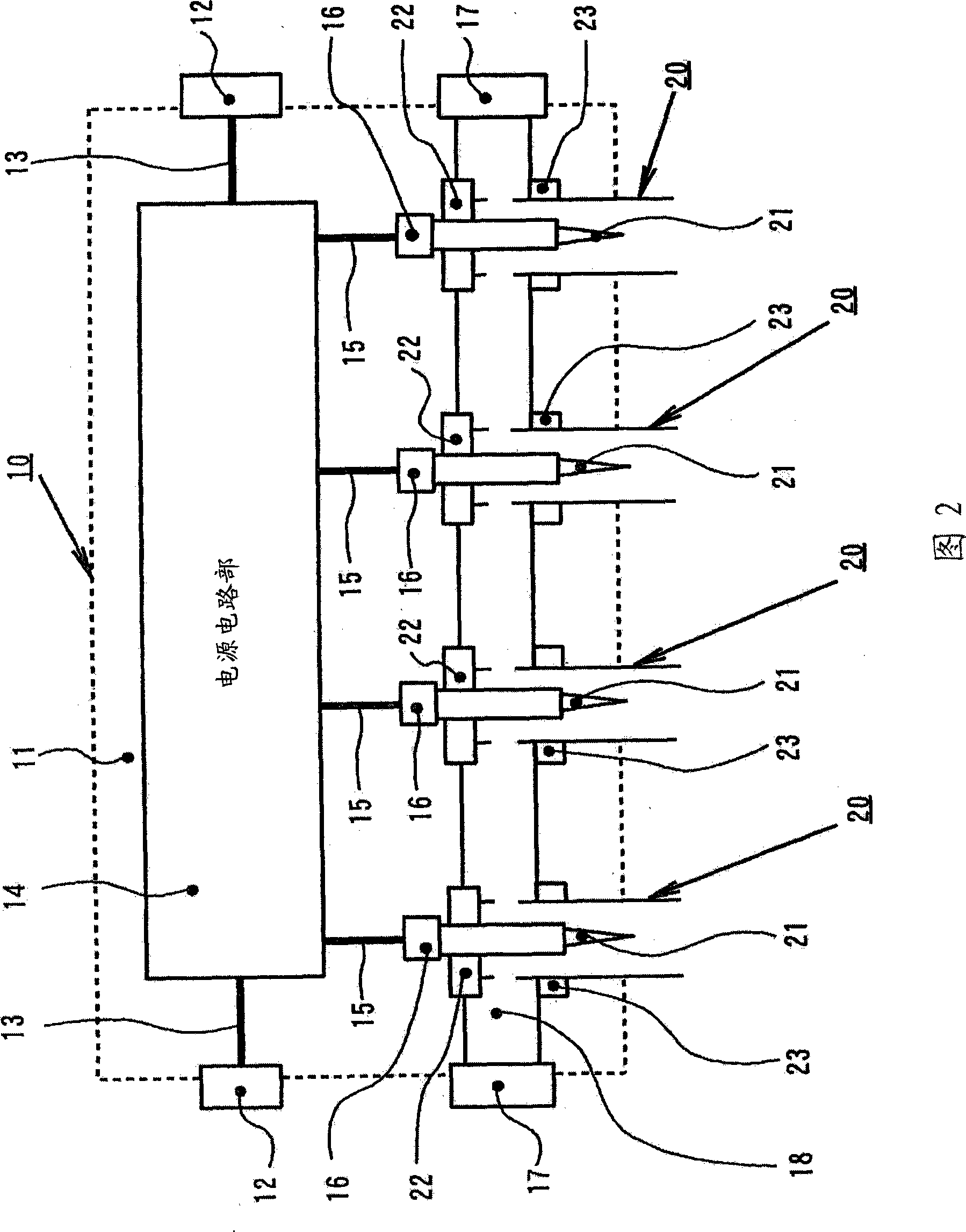
[0037] FIG. 1 is an external view of an ion generator equipped with an electrode unit according to this embodiment. FIG. 2 is an internal block diagram of an ion generator including an electrode unit according to this embodiment. When explaining ion generator 1 here, regard the left-right direction of ion generator 1 of Fig. The left-right direction of 1 is demonstrated as the depth direction of the ion generator 1. As shown in FIG. 1 , the ion generator 1 has an ion generator body 10 and an electrode unit 20 . In use, the power supply line 30 and the air supply line 40 are connected to supply power and clean air.

[0038] Next, the structure of the ion generator main body 10 is demonstrated.

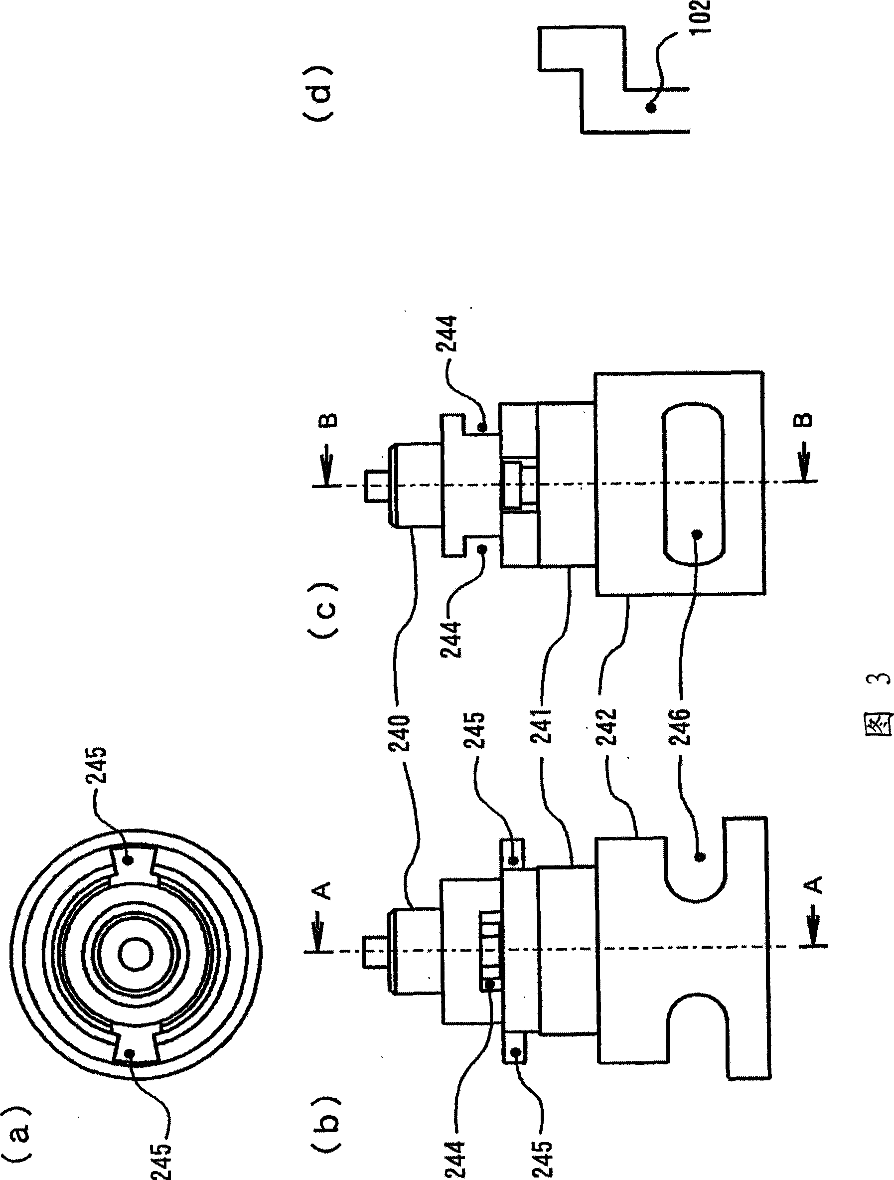
[0039] As shown in Figure 2, the io...


PUM


Abstract

The present invention provides an electrode unit and an ion generator with the electrode unit. The electrode unit increses performance-price ratio through simplifying the structure and reducing cost and prevent recombination through increasing the injecting velocity for increasing the static eliminating capacity. The electrode unit (20) comprises the following components: a needle electrode (21) which is provided with a sharp front end (210) that is approximate conical; a unit body (24) which is provided with a storing space (248) that covers the periphery of needle electrode (21) and an injecting opening (251) from which the sharp front end (210) of the needle electrode (21) projects. The storing space (248) comprises a conical injecting space (249) which is higher than the sharp front end (210) of the needle electrode (21) and has a vertex angle above the vertex angle of the sharp front end (210). The ion generator (1) is installed with a plurality of electrode units (20).

Description

technical field [0001] The present invention relates to an electrode unit for corona discharge and an ion generator having the electrode unit. Background technique [0002] As a bar-type ion generator (Ionaiza) in the prior art, there is one that applies high voltage to needle-shaped discharge electrodes (discharge needles) to generate positive ions and negative ions in the air (hereinafter referred to as ions when positive ions and negative ions are collectively referred to as ions) , and clean air and ions are sprayed to the electrostatically charged object to eliminate static electricity by a corona discharge ion generator. As an example of this static elimination object, a plate-shaped glass substrate etc. are mentioned, for example. The glass substrate is, for example, a substrate applied to a TFT (Thin Film Transistor) liquid crystal panel, a PDP (Plasma Display), or an LCD (Liquid Crystal Display). [0003] Such corona discharge type ionizers are roughly classified ...

Claims


Application Information

Patent Timeline
Patent Type & Authority Applications(China)
IPC IPC(8): H01T23/00H01T19/04
CPCH01T19/04H01T23/00H05F3/04
Inventor 寺崎靖则入江史崇
Owner HUGLE ELECTRONICS
Why Eureka
Try Eureka