
Voltage level clamping circuit and comparator module

A voltage level, clamping circuit technology, applied in the field of high-speed comparator modules, can solve problems such as damage to the driving integrated circuit 100 and increase in product cost, etc.

Inactive Publication Date: 2009-04-01
ILI TECHNOLOGY CORPORATION
View PDF0 Cites 6 Cited by
  • Summary
  • Abstract
  • Description
  • Claims
  • Application Information

AI Technical Summary

Problems solved by technology

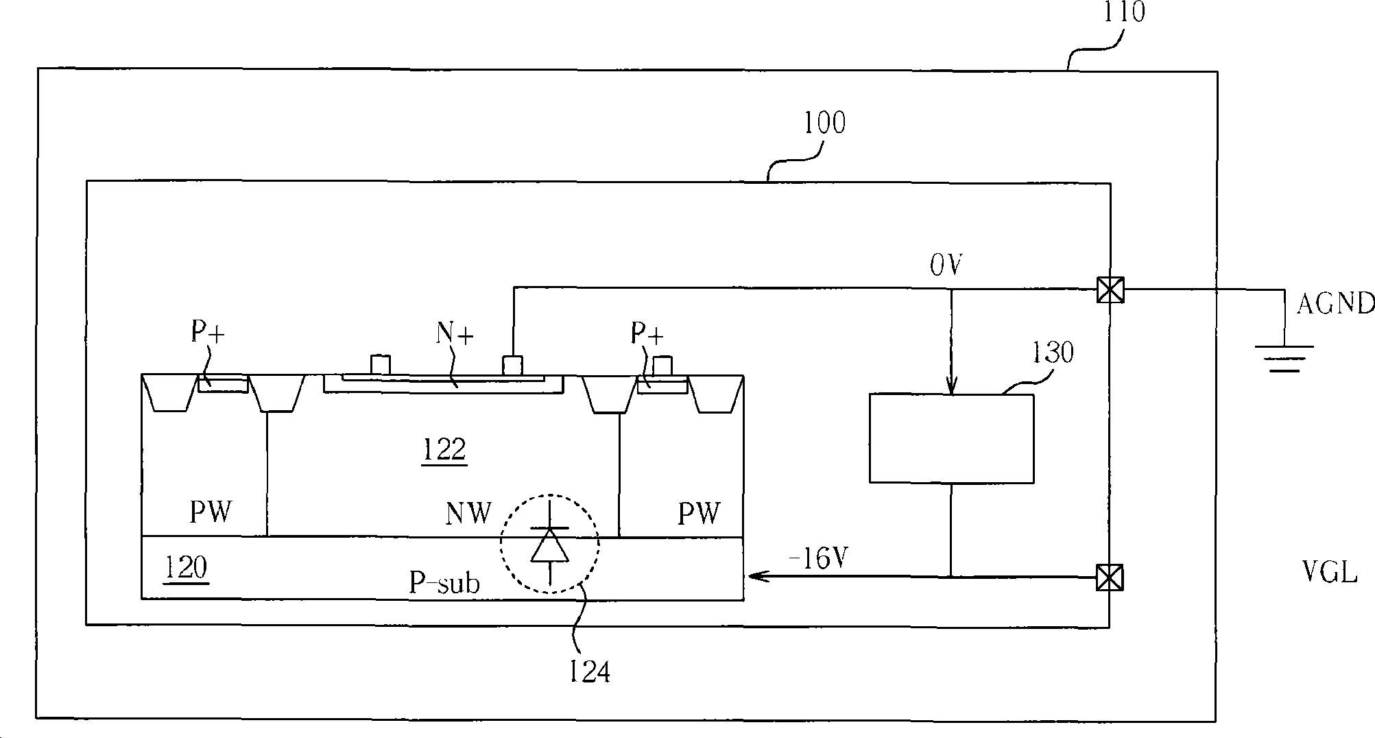
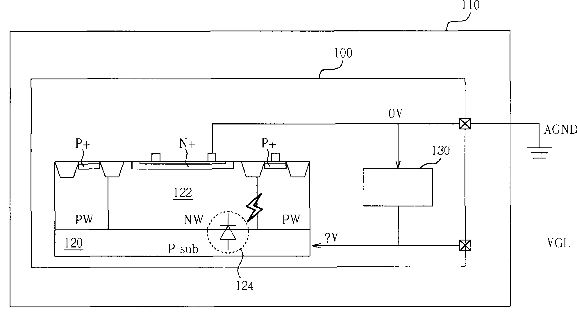
However, when the driving integrated circuit 100 is just started, the negative bias voltage required by the P-type substrate 120 has not yet been formed, and if an external voltage source VGL has a positive voltage at this time, the positive voltage will go forward. Bias (forwardbias) a parasitic diode (parasiticdiode) 124 between the P-type substrate 120 and the N-type well (N well) 122, thereby generating a latchup phenomenon (latchup) and causing damage to the driver integrated circuit 100, please refer to figure 2 , figure 2 Shown is another simplified block diagram of the driving integrated circuit 100 and the circuit board 110 according to the known technology, wherein the voltage level of the P-type substrate (Psubstrate) 120 of the driving integrated circuit 100 is in a start-up operation During
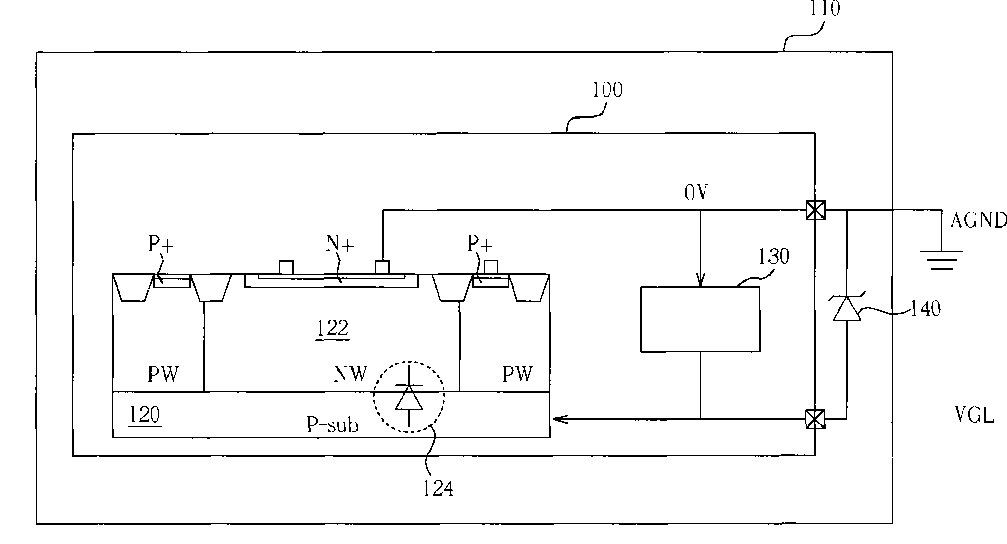
[0003] Please refer to image 3 , image 3 Shown is still another simplified block diagram of a conventional liquid crystal display panel driver integrated circuit 100 and circuit board 110 according to the known technology. In order to solve the aforementioned problems, the known technology adds a driver integrated circuit 100 outside Schottky diode (Schottky diode) 140, so that when the voltage level of the external voltage source VGL is greater than 0.3 volts (that is, when the ground voltage source AGND is smaller than the external voltage source VGL), the Schottky diode 140 will be is turned on to clamp the voltage level of the external voltage source VGL, so as to prevent the P-type substrate 120 inside the drive integrated circuit 100 from being subjected to an excessively high forward bias and cause a latch-up phenomenon. However, due to this well-known The technical circuit structure needs to add additional external components, so there will be a problem of increased product cost

Method used


Image

  • Voltage level clamping circuit and comparator module
  • Voltage level clamping circuit and comparator module
  • Voltage level clamping circuit and comparator module

Examples


Embodiment Construction

[0049] In this specification and the scope of claims, certain words are used to refer to specific components, but those with ordinary knowledge in the field should understand that hardware manufacturers may use different terms to refer to the same component. This specification and claims It is required not to use the difference in name as the way to distinguish components, but to use the difference in function of the components as the criterion for distinguishing. The "comprising" mentioned in the entire specification and claims is an open term. Therefore, it should be interpreted as "including but not limited to". In addition, the word "coupled" includes any direct and indirect electrical connection means. Therefore, if the text describes a first device coupled to a first Two devices means that the first device can be directly electrically connected to the second device, or indirectly electrically connected to the second device through other devices or connection means.

[00...


PUM


Abstract

The invention discloses a voltage level strangulation circuit which can be arranged in an integrated circuit and a high-speed comparator module. The integrated circuit comprises a parasitic diode which is coupled between a first voltage source and a second voltage source. The voltage level strangulation circuit comprises a switch module and a comparator module; wherein, the switch module is coupled in the first voltage source and the second voltage source; the comparator module is provided with an output endpoint which is coupled in the switch module, a first input endpoint which is coupled in the first voltage source and a second input endpoint which is coupled in the second voltage source, and is used for comparing the voltage level of the first voltage source and the voltage level of the second voltage source so as to generate an output signal and conveys the output signal to the switch module so as to control the conducting state of the switch module for selectively clamping the voltage level of the second voltage source.

Description

technical field [0001] The present invention relates to a voltage level clamping circuit and a comparator module, in particular to a voltage level clamping circuit and a high-speed comparator module that can be arranged inside an integrated circuit. Background technique [0002] Please refer to figure 1 , figure 1 Shown is a simplified block diagram of a driving integrated circuit 100 and a circuit board 110 of a conventional liquid crystal display (LCD) panel according to known technologies, wherein the P-type substrate (P substrate) 120 of the driving integrated circuit 100 The voltage level is during a normal operation. Such as figure 1 As shown, in the driving integrated circuit 100, since the driving integrated circuit 100 is a high-voltage integrated circuit design, in order to ensure the normal operation of the driving integrated circuit 100, it is common for the P-type substrate 120 to use a negative bias voltage (for example, negative 16 volts). way, and the neg...

Claims


Application Information

Patent Timeline
Patent Type & Authority Applications(China)
IPC IPC(8): H03G11/02H03K5/24G09G3/36
Inventor 王燕晖张清荣
Owner ILI TECHNOLOGY CORPORATION
Learn More