Multipath output circuit

A multi-channel output and circuit technology, applied in the direction of electrical components, electronic switches, pulse technology, etc., can solve the problems of high quality and low price, clumsy use, poor contact, etc., and achieve high reliability, light use, and cost-effective improvement Effect

Inactive Publication Date: 2009-04-01
SHENZHEN H&T INTELLIGENT CONTROL
View PDF0 Cites 5 Cited by
  • Summary
  • Abstract
  • Description
  • Claims
  • Application Information

AI Technical Summary

Problems solved by technology

It is simple to use the first method, but the problem is: contact oxidation leads to poor contact, and it is clumsy to use due to its large size
Although high intelligence can be achieved by using the second method

Method used


Image

  • Multipath output circuit
  • Multipath output circuit
  • Multipath output circuit

Examples


Example Embodiment

Specific implementation one

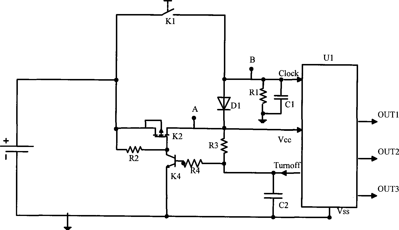
[0020] like figure 1 As shown, a multiplex output circuit includes a first switch K1, a start-up unit, a self-locking unit, a shutdown signal buffer unit and a shift unit U1. The first switch K1 is connected to the starting unit and is connected across the input and output ends of the self-locking unit. The input of the self-locking unit is coupled with the power supply, and the output is coupled with the power supply terminal Vcc of the shifting unit U1, so One end of the shutdown signal buffer unit is coupled to the shutdown signal output end of the shift unit U1, and the other end is coupled to the power supply, and the connection point between the first switch K1 and the start-up unit is coupled to the clock input end of the shift unit U1, so The effective output of the shift unit U1 is shifted backward by one bit every time the clock input terminal of the shift unit U1 receives a pulse. The power source may be a battery.

[0021] like figu...

Example Embodiment

Specific embodiment two

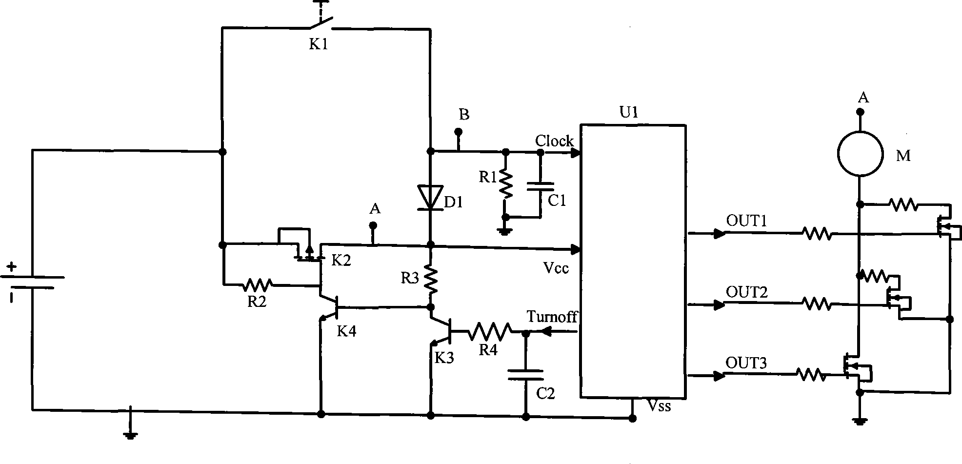
[0031] like figure 2 As shown, the difference between this specific embodiment and the specific embodiment 1 is: in this specific embodiment, the effective output of the shift unit U1 is a high level, this specific embodiment needs to add a reverse unit, the reverse The unit is coupled between the control terminal of the self-locking unit and the shutdown signal output terminal of the shift unit U1. Moreover, the circuit structure of the self-locking unit of this specific embodiment is slightly different from that of the self-locking unit of the first embodiment. This will be further explained below.

[0032] like figure 2 As shown, the startup unit includes a first diode D1, and the self-locking unit includes a second switch tube K2, a third resistor R3, a second resistor R2, and a fourth switch tube K4.

[0033] like figure 2 As shown, the anode of the first diode D1 is connected to the first switch K1, the cathode is connected to the second ...

Example Embodiment

Specific embodiment three

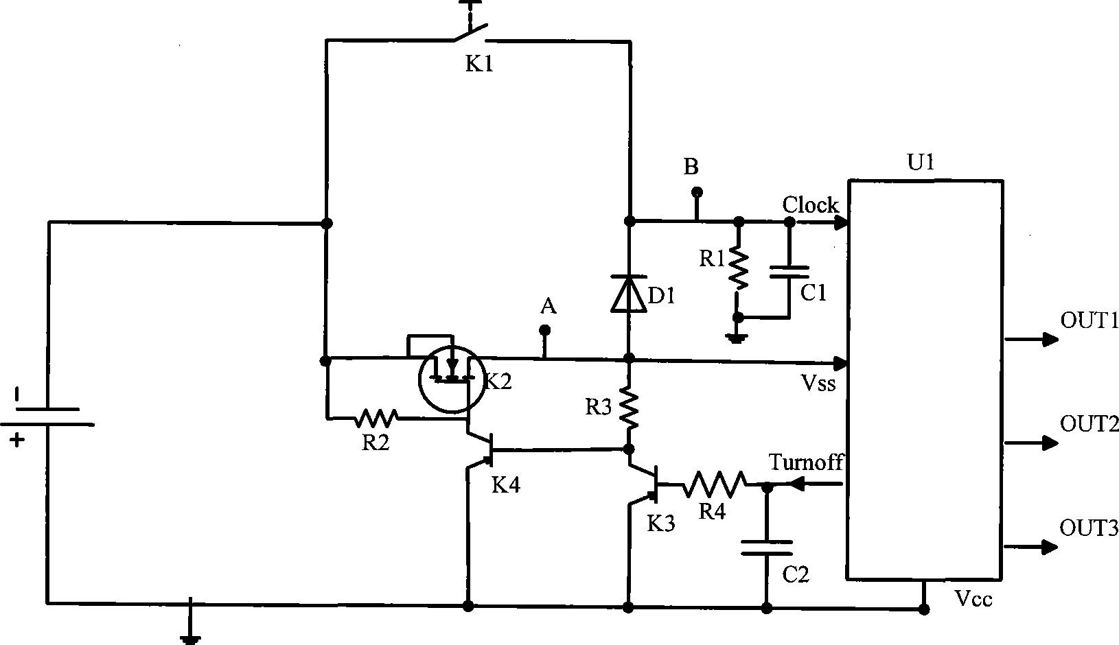
[0041] like image 3 As shown, the difference between this specific embodiment and the first specific embodiment is that: in this specific embodiment, the circuit structure is of negative logic, and the positive electrode of the power supply is grounded. The circuit structure of this specific implementation is slightly different from the circuit structure of the specific implementation manner, and the details are as follows:

[0042] like image 3 As shown, the startup unit includes a first diode D1, and the self-locking unit includes a second switch tube K2, a third resistor R3, a second resistor R2, a fourth resistor R4, and a fourth switch tube K4; the The cathode of the first diode D1 is connected to the first switch K1, the anode is connected to the second end of the second switch tube K2, the first end of the second switch tube K2 is connected to the negative pole of the power supply, and the second switch tube K2 is the second The terminal ...


PUM


Abstract

The invention discloses a multiplexed output circuit which comprises a first switch, a start-up unit, a self-locking unit, a shutdown signal buffer cell and a shifting unit. The first switch is connected with the start-up unit, and then is spanned on the input end and the output end of the self-locking unit. The input of the self-locking is coupled with an electric power source while the output is coupled with a power supplying end of the shifting unit. One end of the shutdown signal buffer cell is coupled with a shutdown signal output end of the shifting unit while the other end is coupled with electrical power source. The conical point between the first switch and the start-up unit is coupled to a clock input end of the shifting unit. After the shifting unit receives a pulse every time at a clock output end of the shifting unit, the actual output of the shifting unit shifts one bit backwards. The circuit can realize one touch key and multiplexed output. Not only the switch of a function tap position is realized but also the thorough shutoff and open of the electric power source is realized. In addition, the one touch key causes that the appearance of products are more beautiful and the use is more convenient.

Description

technical field [0001] The invention relates to a multiplex output circuit. Background technique [0002] In the past, especially for battery-powered handheld devices, such as electric shavers, electric massagers, etc., to achieve multi-function or multi-gear switching, there are generally two methods: one is to use a mechanical multi-gear switch, the other One is to use a single-chip microcomputer to realize switching through one or more buttons. Using the first method is simple, but the problem is that the contact is oxidized, resulting in poor contact, and it is bulky and clumsy to use. Although the second method can achieve high intelligence, the cost is high, and it cannot achieve the purpose of high quality and low price. Moreover, to completely turn off the power supply, the battery must be removed or an additional mechanical switch must be added. SUMMARY OF THE INVENTION [0003] In order to overcome the above deficiencies, the present invention proposes a multi-...

Claims


Application Information

Patent Timeline
IPC IPC(8): H03K17/296
Inventor 李先虎刘建伟蒋洪波
Owner SHENZHEN H&T INTELLIGENT CONTROL
Why Eureka
Try Eureka