
Data transmission method for orthogonal frequency division multiplexing system

A data transmission method and orthogonal frequency division technology, applied in the data transmission field of an orthogonal frequency division multiplexing system, can solve problems such as large signaling overhead, poor filling efficiency, and changes, and achieve low signaling overhead and complex signaling. Low intensity and the effect of reducing the interference of adjacent cells

Active Publication Date: 2011-12-28
ZTE CORP
View PDF0 Cites 0 Cited by
  • Summary
  • Abstract
  • Description
  • Claims
  • Application Information

AI Technical Summary

Problems solved by technology

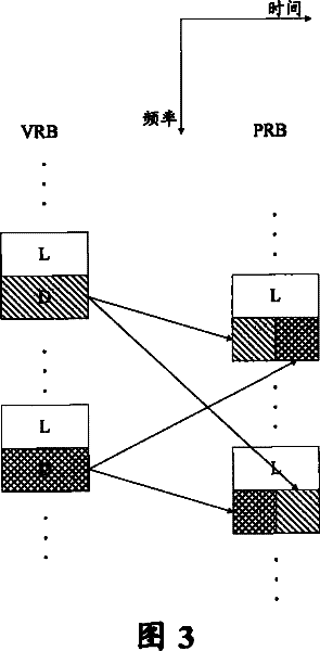
[0004] The currently commonly used DVRB-DPRB mapping method is to pre-determine the position of DPRB in the entire system bandwidth according to the system bandwidth or the total number of DPRB, and the base station indicates the distribution of DPRB and its subcarriers allocated to users through control signaling. The disadvantage is that the DVRB-DPRB mapping process changes with the total number of DPRBs or the system bandwidth, that is to say, once the parameters change, the position of the corresponding DPRB in the system bandwidth may also change
Although the base station can dynamically send the DPRB number information to each user performing distributed transmission, this will cause a large signaling overhead. If the DPRB number information is sent in a semi-static way, the filling efficiency will be very high. In addition, for users performing persistent scheduling (or semi-persistent scheduling) services, it is not allowed to change the physical resources used for data transmission during the transmission process, so the change of the mapping position of DPRB that may be caused by the existing technology is not Conducive to supporting continuous scheduling business

Method used


Image

  • Data transmission method for orthogonal frequency division multiplexing system
  • Data transmission method for orthogonal frequency division multiplexing system
  • Data transmission method for orthogonal frequency division multiplexing system

Examples


Embodiment Construction

[0016] The specific implementation manners of the present invention will be described in detail below with reference to the accompanying drawings.

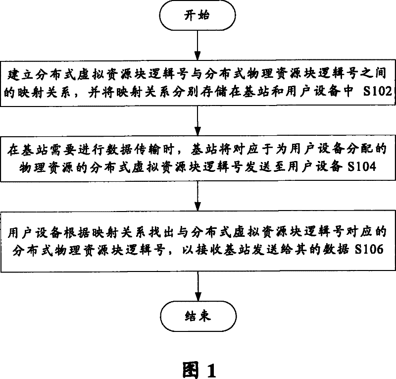
[0017] refer to figure 1 , illustrating a data transmission method for an OFDM system according to an embodiment of the present invention. Such as figure 1 As shown, the data transmission method includes the following steps: S102, establishing a mapping relationship between the logical number of the distributed virtual resource block and the logical number of the distributed physical resource block, and storing the mapping relationship in the base station and the user equipment respectively; S104, When the base station has data to send to the user equipment, the base station sends the logical number of the distributed virtual resource block corresponding to the physical resource allocated for the user equipment to the user equipment; and S106, the user equipment finds the distributed virtual resource block according to the mappin...


PUM


Abstract

The invention discloses a data transmission method used in an OFDM system, comprising the following steps: S102, establishing a mapping relationship between a logical number of a distributed virtual resource block and a logical number of a distributed physical resource block, and The mapping relationship is stored in the base station and the user equipment respectively; S104, when the base station needs to perform data transmission, the base station sends the distributed virtual resource block logic number corresponding to the physical resource allocated for the user equipment to the user equipment; and S106, the user equipment Find out the logical number of the distributed physical resource block corresponding to the logical number of the distributed virtual resource block according to the mapping relationship, so as to receive the data sent therefrom by the base station. The invention has the advantages of small signaling overhead, low complexity, effectively reducing the interference of adjacent cells, and better supporting the business type of continuous scheduling.

Description

technical field [0001] The present invention relates to the communication field, and more specifically relates to a data transmission method used in an orthogonal frequency division multiplexing system. Background technique [0002] Orthogonal Frequency Division Multiplexing (OFDM for short) technology is one of the main candidate solutions for future wireless communication technologies. OFDM technology divides a given channel into many orthogonal subcarriers in the frequency domain, modulates signals on each subcarrier separately, and transmits each subcarrier in parallel. In this way, although the frequency response curve of the wireless channel is non-flat and has frequency selectivity, the frequency response within each subcarrier is relatively flat, and what is carried out on each subcarrier is narrowband transmission, and the signal bandwidth is smaller than the channel bandwidth, so that Greatly eliminate the interference between signal waveforms. Since each sub-car...

Claims


Application Information

Patent Timeline
Patent Type & Authority Patents(China)
IPC IPC(8): H04L5/06H04L27/26
Inventor 田刚戴博郁光辉
Owner ZTE CORP
Learn More