Casing and method for manufacturing same, and electronic device

A manufacturing method and technology of electronic equipment, which is applied to electrical equipment shells/cabinets/drawers, sub-office equipment, circuits, etc., can solve problems such as insufficient antenna storage space, and achieve the effect of improving appearance

Inactive Publication Date: 2009-04-01
KK TOSHIBA
View PDF5 Cites 7 Cited by
  • Summary
  • Abstract
  • Description
  • Claims
  • Application Information

AI Technical Summary

Problems solved by technology

However, the antenna storage space is not very sufficient

Method used


Image

  • Casing and method for manufacturing same, and electronic device
  • Casing and method for manufacturing same, and electronic device
  • Casing and method for manufacturing same, and electronic device

Examples


Embodiment Construction

[0020] Hereinafter, embodiments of the present invention will be described with reference to the drawings.

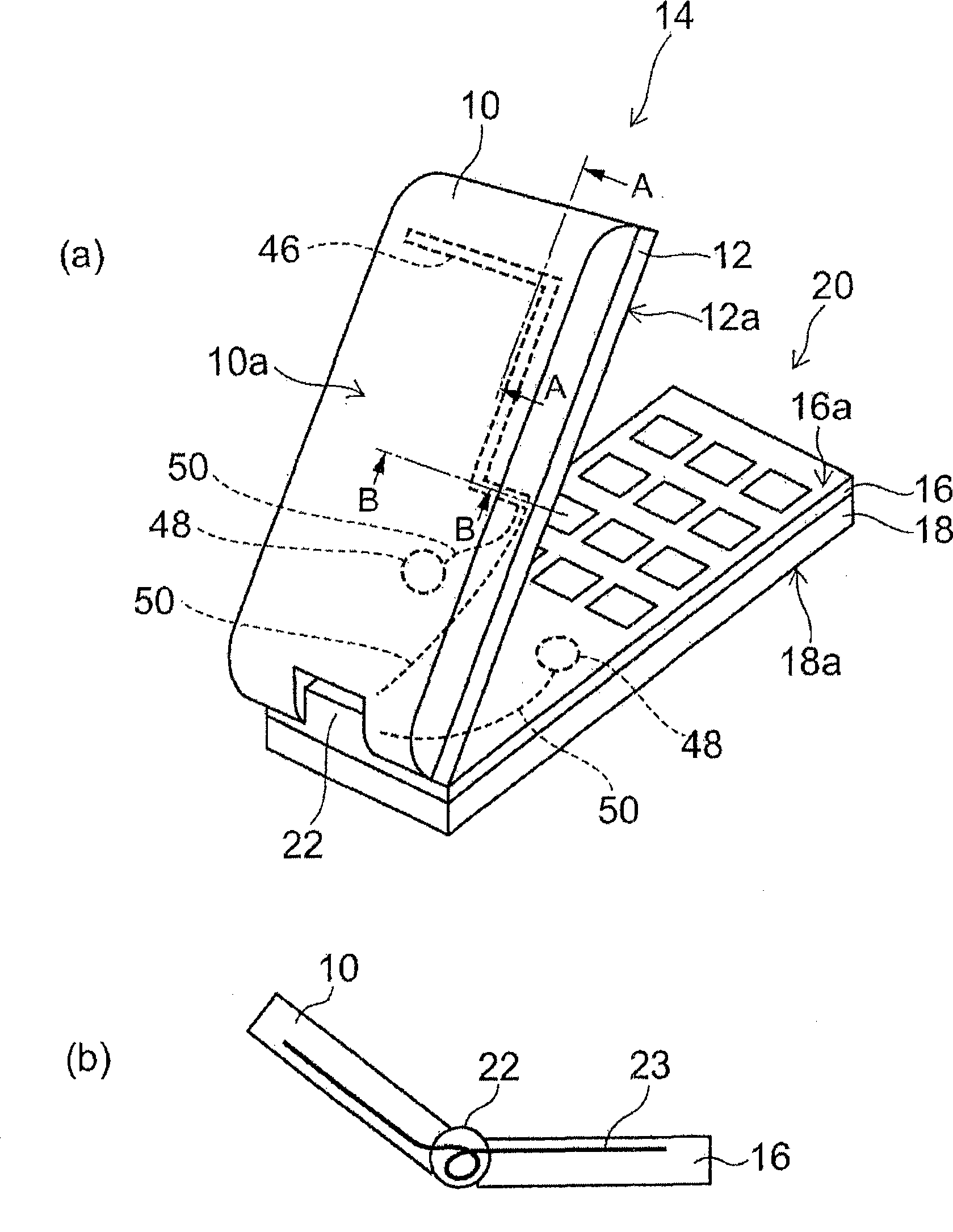
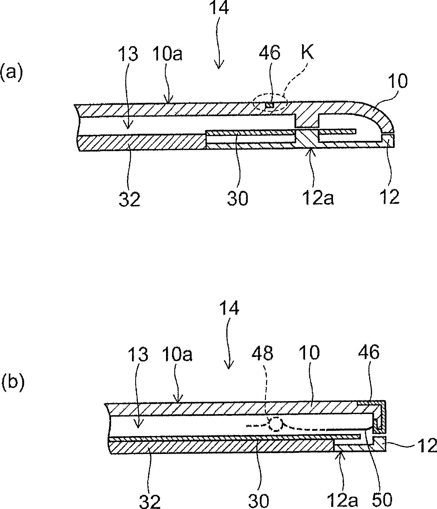
[0021] figure 1 represents the electronic device in the embodiment of the present invention, figure 1 (a) is a model stereogram, figure 1 (b) is a schematic cross-sectional view showing an example of electrical connection using a flexible substrate. A first housing 10 comprising a molded body is combined with a second housing 12 comprising a molded body. Assuming that the portable device is, for example, a mobile phone, the first housing 10 and the second housing 12 are combined to form a display unit 14 . In addition, the third housing 16 and the fourth housing 18 are combined to form the operation unit 20 .

[0022] figure 1 (a) shows a foldable mobile phone in which the display unit 14 and the operation unit 20 are mechanically or electrically connected through the hinge unit 22 . As the overlapping method, there are sliding type, rotating type, etc., but the p...


PUM


Abstract

A casing includes a molded body provided with a recess, a conductive layer provided in the recess, and a protection film provided to cover at least a non-recessed region in a surface of the molded body provided with the recess and a surface of the conductive layer. The protection film extends generally evenly over the non-recessed region and the surface of the conductive layer. A method manufacturing the same and an electronic device including the casing are provided.

Description

technical field [0001] The present invention relates to a casing, a manufacturing method thereof, and an electronic device. Background technique [0002] With the miniaturization requirements of electronic devices such as mobile phones and notebook computers, it is necessary to increase the freedom of antenna design even if the space is small. [0003] In this case, for example, inside the casing of a mobile phone, if a metal plate, in-mold processing, or a built-in antenna formed by a MID (Molded Interconnect Device: Molded Interconnect Device) is arranged between the substrate and the casing, the installation space will be reduced. will increase. In addition, in many cases, ribs, protrusions, and the like are arranged inside the case, which restricts the arrangement and shape of the antenna. [0004] On the other hand, if the antenna is arranged on the outer surface of the housing, although the installation space can be easily ensured, the thickness of the antenna tends ...

Claims


Application Information

Patent Timeline
Patent Type & Authority Applications(China)
IPC IPC(8): H05K5/00H01Q1/22H01Q1/40H01Q1/38H04M1/02
CPCH04M1/0283H04M1/0214H01Q1/40H01Q1/243
Inventor 本田朋子高桥不二男
Owner KK TOSHIBA
Why Eureka
Try Eureka