Color resolution method and video image processing device

A technology for color decomposition and image processing equipment, which is applied in the field of color decomposition methods and image processing equipment, and can solve the problem of not specifying the LUT preparation method.

Inactive Publication Date: 2009-04-01
CANON KK
View PDF9 Cites 13 Cited by
  • Summary
  • Abstract
  • Description
  • Claims
  • Application Information

AI Technical Summary

Problems solved by technology

However, the specific preparation method of the LUT is not explained

Method used


Image

  • Color resolution method and video image processing device
  • Color resolution method and video image processing device
  • Color resolution method and video image processing device

Examples


no. 1 example

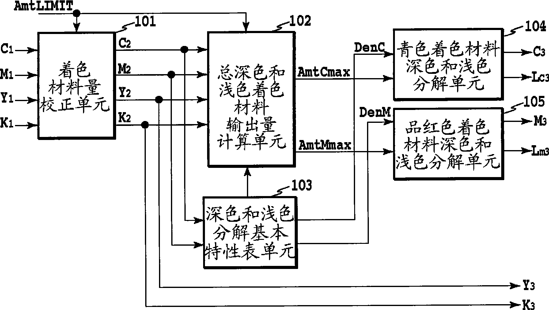
[0078] figure 1 is a block diagram showing the structure of color decomposition processing according to one embodiment of the present invention. Color decomposition is performed to convert coloring material values ​​(coloring material value signals) of four coloring materials of basic colors C, M, Y, and K into C, M, Y including light colors having the same tone and low density Coloring material values ​​(coloring material value signals) of the six coloring materials of , K, Lc, and Lm.

[0079] In the drawing, a coloring material amount correction unit 101 performs coloring material amount correction on C1, M1, Y1, and K1 obtained from R, G, and B image data each of eight bits, and obtains C2, M2, Y2 and K2. Well-known methods are used for color decomposition to obtain C1, M1, Y1 and K1 from the R, G and B image data. For example, for grid points on a predetermined line connecting vertices of cubes in the RGB space, grid point data (colorimetry value) is obtained based on...


PUM


Abstract

In a case wherein a color separation table is prepared, color separation is provided, so that the density characteristic to be output is maintained, and the total colorant amount is not beyond the limit value of the total colorant amount. Further, the optimal color separation is performed while taking into account the colorant amount, and the colorant amount of a light color is adjusted in the entire color range to control granularity and consumption of the colorant amount. A color separation method comprising: a step of calculating the total colorant amount by employing a relationship between a total colorant amount limit value and a colorant amount, that includes a colorant amount for a colorant other than the dark colorant and the light colorant; a step of calculating a density; and a step of employing the total colorant amount and the density to calculate the colorant value signals.

Description

technical field [0001] The present invention relates to a color decomposition method and image processing apparatus, and more particularly to a color decomposition performed when converting an image signal into a signal representing the amount of a coloring material such as ink or toner. Background technique [0002] Figure 49 An exemplary conventional method for color-decomposing an image signal to obtain a signal of a coloring material to be used by a printing apparatus such as a printer is shown. [0003] Figure 49 It is a diagram showing the configuration of an image system that performs color decomposition. R, G, and B represent red, green, and blue image signals, respectively. In addition, C, M, Y, K, Lc, and Lm represent cyan, magenta, yellow, black, light cyan, and light magenta signals, respectively. The control unit 4901 performs predetermined color decomposition processing, and converts image signals R0, G0, and B0 and image signals C0, M0, Y0, and K0 received...

Claims


Application Information

Patent Timeline
IPC IPC(8): H04N1/46B41J2/21B41J2/525G06T1/00H04N1/60
Inventor 斋藤和浩高桥正臣
Owner CANON KK
Why Eureka
Try Eureka