Waterless decorating machine
A printing machine and print head technology, applied in printing, typewriters, printing devices, etc., can solve problems such as false pasting, distance changes, and inability to print flower patterns accurately, so as to improve printing quality and avoid deviation.
- Summary
- Abstract
- Description
- Claims
- Application Information
AI Technical Summary
Problems solved by technology
Method used
Image
Examples
Embodiment 1
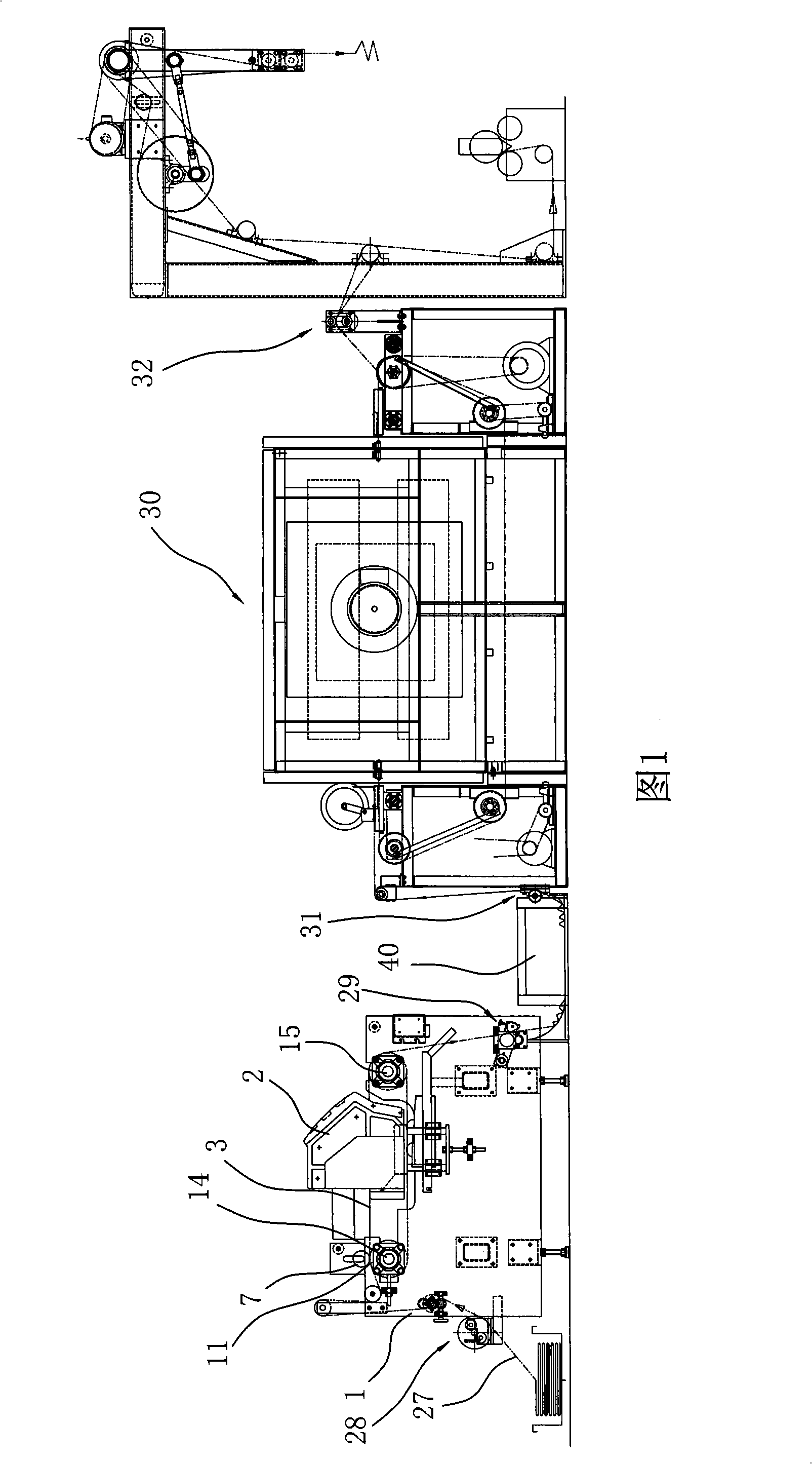
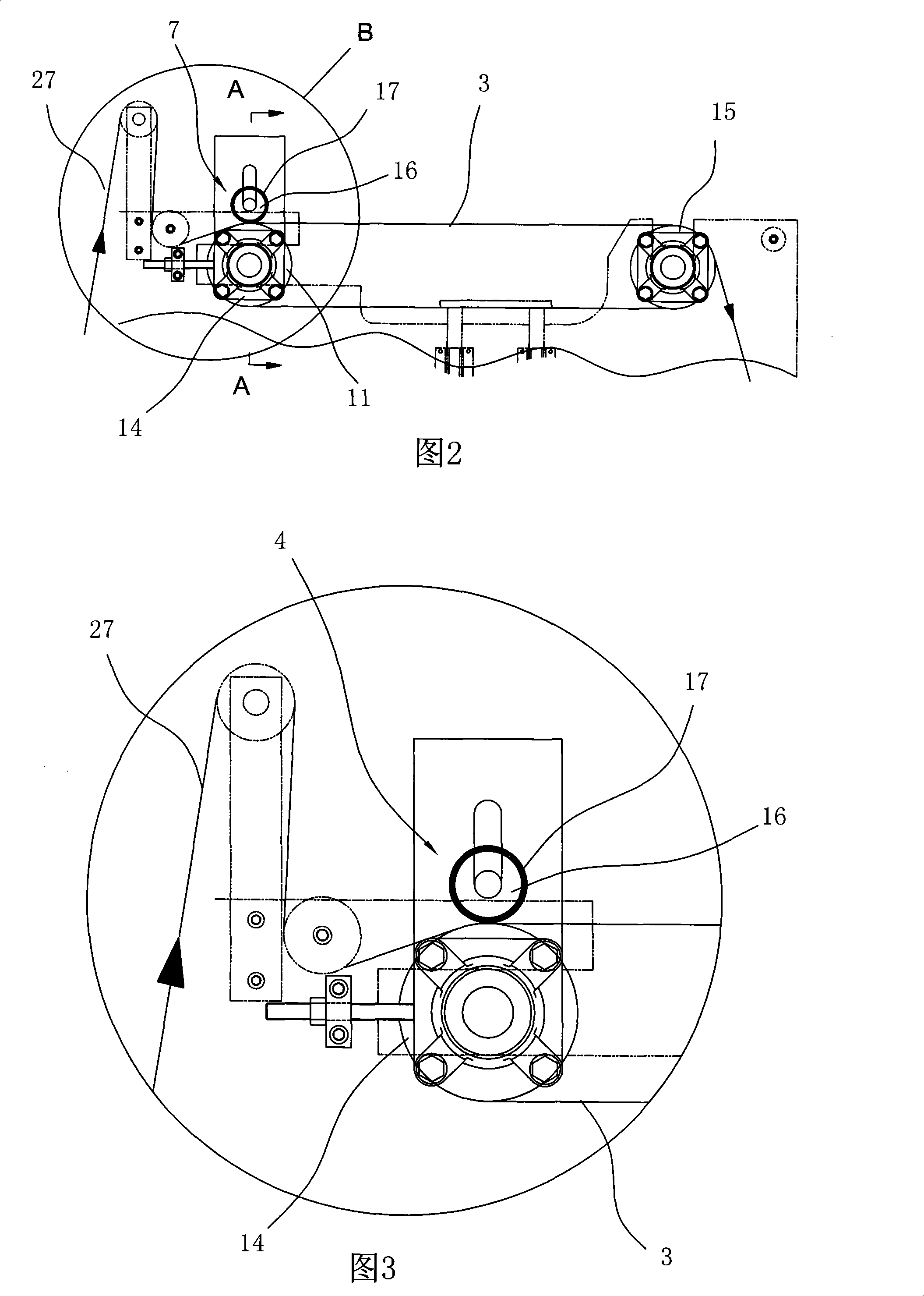
[0059] Embodiment 1: waterless printing machine, as shown in Fig. 1-Fig. 3, Fig. 6-Fig. The cloth guide transmission part 3 is arranged in cooperation, and the base 1 is provided with a cloth guide device, a cloth guide transfer part 3 and a baking device matched with the cloth guide device, and the cloth guide transfer part 3 is arranged on the base 1 The transmission rollers on the top of the transmission part cooperate with each other, and the two side edges of the cloth guide transmission part 3 are equipped with a guide belt straightening mechanism, and a flexible cloth patching device is also equipped on the upper surface of the cloth guide transmission part 3 above the transmission part transmission roller; Below the working area where the cloth guide conveying member 3 cooperates with the printing nozzle is provided a strip roller 4 supporting the cloth guiding conveying member, and the setting position of the strip roller 4 also corresponds to the stroke position of th...
Embodiment 2
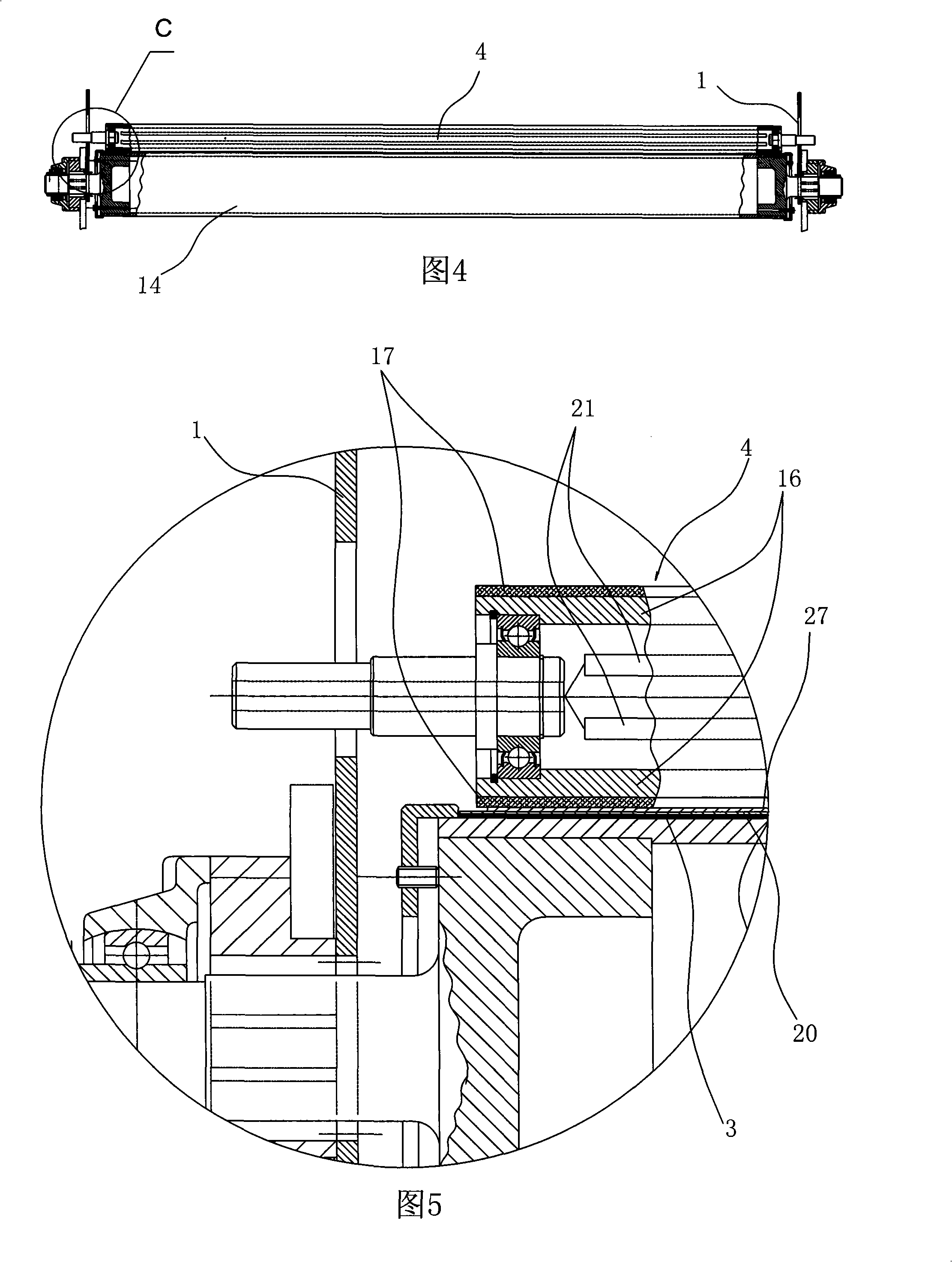
[0074] Embodiment 2: waterless printing machine, as shown in Fig. 4 and Fig. 5, the upper surface of guide cloth conveying part 3 is provided with heat-sensitive adhesive adhesive layer 20, and flexible patching roller 7 is to cooperate with adhesive layer 20 The flexible heating patch roller has an electric heating element 21 inside the roller 16 . All the other structures are the same as in Embodiment 1
Embodiment 3
[0075] Embodiment 3: waterless printing machine, the straightening guide 11 is a circular ring respectively arranged on the two ends of the driven roller 14 and the driving roller 15, and the straightening guide 11 is formed on the curved surface where the cloth guide transmission part 3 is located. The first part is a protruding ring, the height of which is greater than the thickness of the cloth guide conveying member 3 . All the other structures are with embodiment 1 or embodiment 1. The accompanying drawings are similar to other embodiments, so the accompanying drawings are omitted.
PUM
 Abstract
Description
Claims
Application Information
 - R&D
- Intellectual Property
- Life Sciences
- Materials
- Tech Scout
- Unparalleled Data Quality
- Higher Quality Content
- 60% Fewer Hallucinations
Browse by: Latest US Patents, China's latest patents, Technical Efficacy Thesaurus, Application Domain, Technology Topic, Popular Technical Reports.
© 2025 PatSnap. All rights reserved.Legal|Privacy policy|Modern Slavery Act Transparency Statement|Sitemap|About US| Contact US: help@patsnap.com


