Vehicle structure for automobile

A body and automobile technology, applied in the direction of bumpers, etc., can solve the problems of collapse and deformation of the crash box, small section modulus, failure to play the role of the crash box, etc., and achieve the effect of preventing bending deformation

Active Publication Date: 2009-04-08
MAZDA MOTOR
View PDF0 Cites 19 Cited by
  • Summary
  • Abstract
  • Description
  • Claims
  • Application Information

AI Technical Summary

Problems solved by technology

[0008] However, when receiving an offset load that is biased to one side in the vehicle width direction, because there are recessed grooves on the side of the crash box, the section modulus is small and the rigidity in the lateral direction is small. It is also very low, making the crash box easily collapsed and deformed
[0009] When the crash box is collapsed and deformed in this way, there is a possibility that the crash energy absorption perfor

Method used


Image

  • Vehicle structure for automobile
  • Vehicle structure for automobile
  • Vehicle structure for automobile

Examples


Example Embodiment

[0059] Hereinafter, embodiments of the present invention will be described in detail based on the drawings.

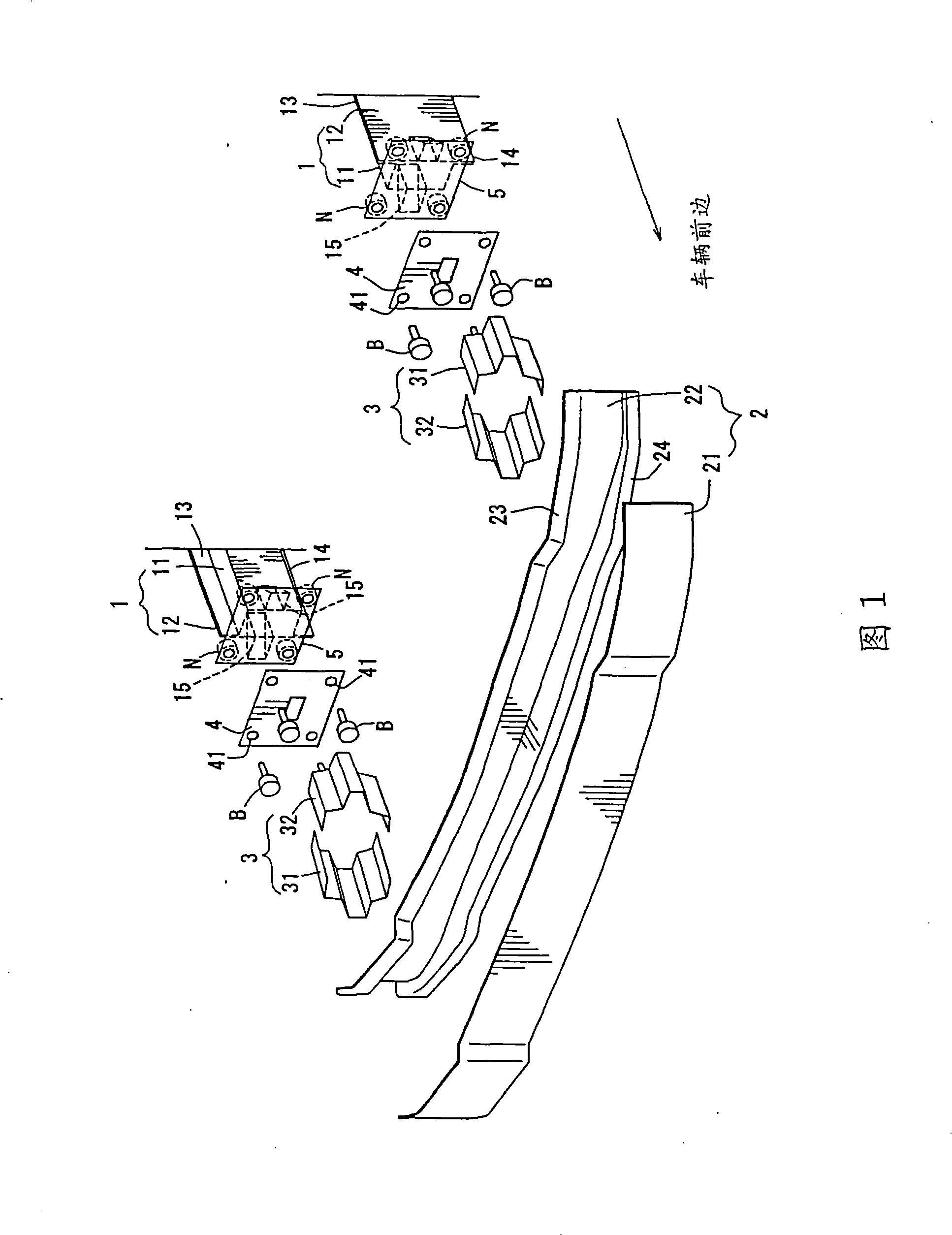
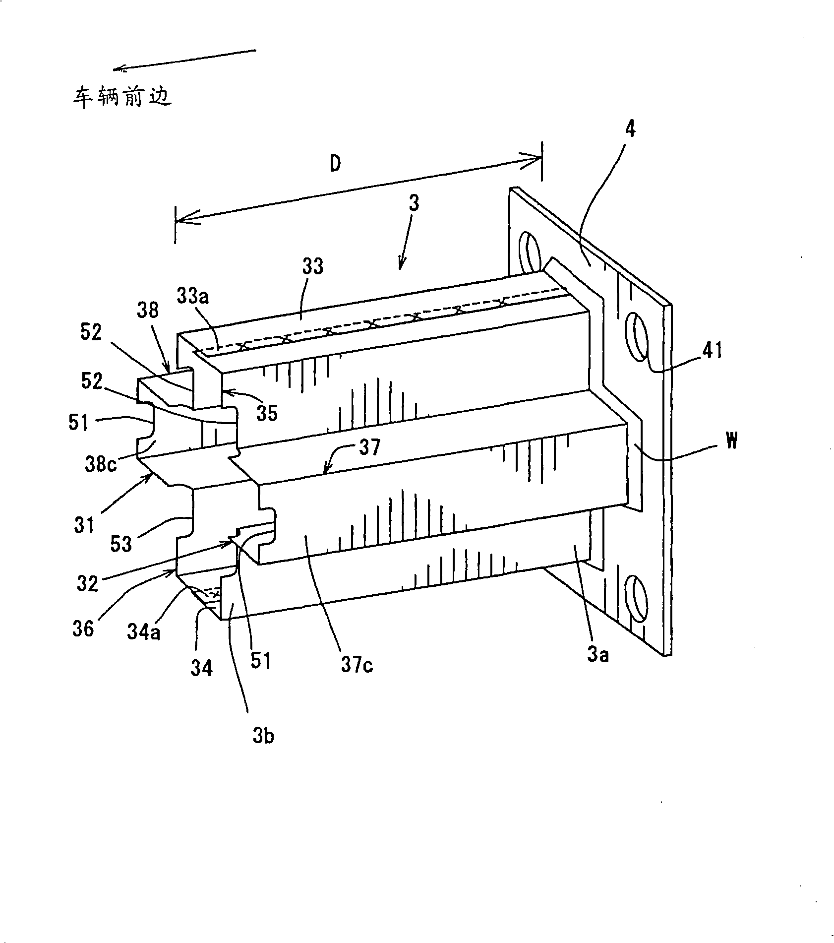
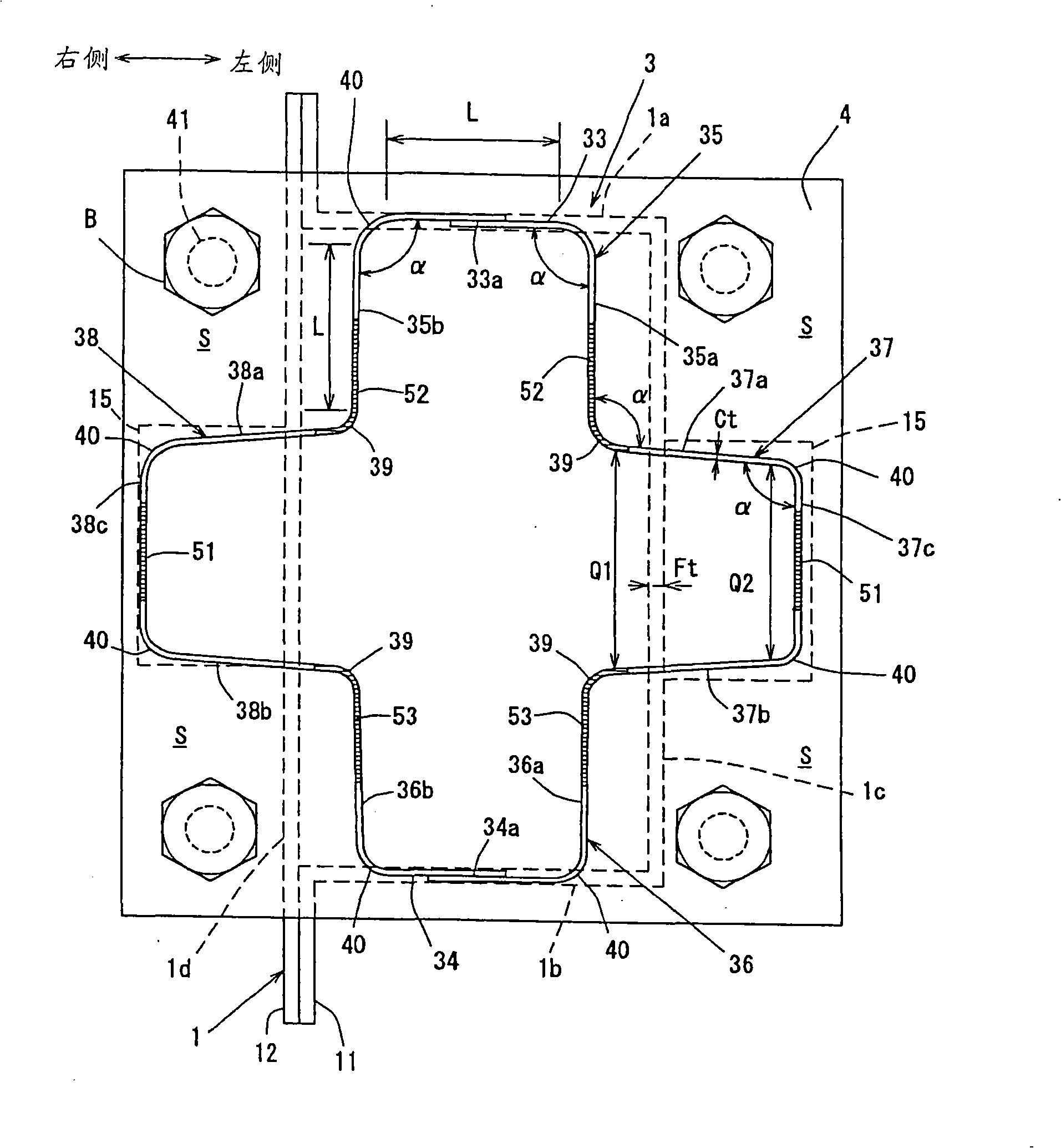
[0060] First, according to Figure 1 to Figure 4 The body structure of the automobile of this embodiment will be described. FIG. 1 is a perspective view of the vehicle body structure of the front part of the vehicle which is disassembled and used in this embodiment; figure 2 It is a perspective view of the whole of the crash box of this embodiment; image 3 It is a front view showing in detail the positional relationship between the crash box on the right side of the vehicle body and the front side frame; Figure 4 It is a perspective view showing the reinforced bracket provided on the front side frame.

[0061] As shown in Figure 1, the vehicle body structure at the front of the vehicle includes a pair of front side frames 1, 1 located on the left and right sides and extending in the front and rear directions of the vehicle, which are closer to the front of the vehicle t...


PUM


Abstract

The invention discloses an automobile body structure. Section of a collision energy-absorbing box (3) is approximately a cross-shaped close section (approximately a cross-shaped box shape), concretely, projecting and approximately rectangular protruding portions (35, 36, 37, 38) are formed on upper edge, lower edge, left edge and right edge, and length (L) of each edge arranging each protruding portion (35, 36, 37, 38) are approximately equal. Angle (alpha) formed by angle portions (39, 40) between each edge is approximately right-angle, namely 90 DEG. So that, the collision energy-absorbing box is arranged in the automobile body structure at front end of body skeleton extended along automobile front-and-rear direction to provide a corrugation deformation generated by the collision energy-absorbing box not only when the automobile suffers load from right side but also when the automobile suffers bias load on vehicle wide direction, thereby assuredly performing collision energy-absorbing property of automobile body structure.

Description

technical field [0001] The present invention relates to a vehicle body structure, in particular to a vehicle body structure in which a crash box is arranged at the front end of a vehicle body frame extending in the front-rear direction of the vehicle. Background technique [0002] Heretofore, there has been known an automobile body structure in which the rigidity in the axial direction (vehicle front-rear direction) is lower than that of the body frame in the axial direction in order to properly absorb the collision energy at the time of vehicle collision. The rigid energy-absorbing box on the vehicle is arranged at the front end of the body frame (front side frame or rear side frame) extending along the front-to-back direction of the vehicle, so that the collision energy-absorbing box produces buckling deformation at the initial stage of collision to absorb the collision. energy. [0003] For example, in the following Patent Document 1, there is described a shock absorbing...

Claims


Application Information

Patent Timeline
IPC IPC(8): B60R19/34
CPCB60R19/34
Inventor 寺田荣小胁三穗中山伸之
Owner MAZDA MOTOR
Why Eureka
Try Eureka