Spinning device

A technology of spinning frame and negative pressure tube, applied in the field of spinning devices, can solve the problems of non-constant frictional resistance, unstable movement of the upper aprons, etc., to achieve the advance of the speed change point, the stable improvement of the yarn evenness quality, and the reasonable control. Effect

Inactive Publication Date: 2011-06-22
潘思敏
View PDF0 Cites 4 Cited by
  • Summary
  • Abstract
  • Description
  • Claims
  • Application Information

AI Technical Summary

Problems solved by technology

[0005] Third: the upper and lower aprons are in close contact with the front ends of the fixed upper and lower pins during operation, so the aprons must overcome their frictional resistance to operate, and this frictional resistance is not constant, so the movement of the upper apron is unstable

Method used


Image

  • Spinning device
  • Spinning device

Examples


Embodiment Construction

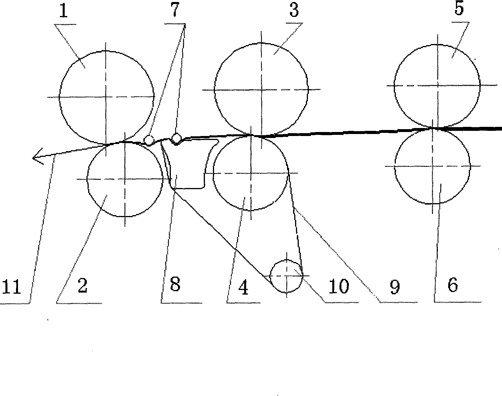
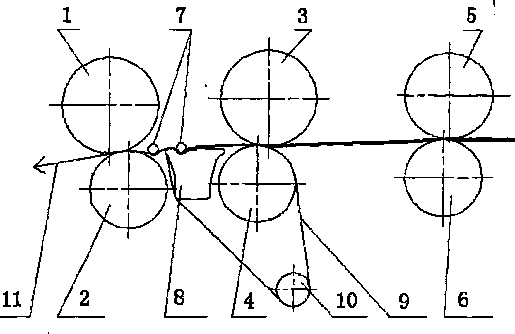
[0012] The technical solution adopted by the present invention to solve the technical problem is: remove the negative pressure tube, the grid ring, the accumulation top roller, the gear, the transmission bridge gear, the pressure rod and the front drafting on the existing compact spinning frame. The upper pin, lower pin, compression spring, upper apron, lower apron and distance block in the area. Between the front jaw and the middle jaw, that is, a group of control rods, negative pressure tubes, and mesh rings are installed in the front drafting area. Among them, the negative pressure tube has a gradually narrowing suction groove at the spinning position, and the negative pressure tube is fixed and does not move; the mesh ring is a porous fabric ring with good air permeability but the fibers cannot pass through, and the mesh ring is wrapped in the negative pressure tube. In the spinning position, the grid ring moves by the transmission of the middle roller. There are grooves ...


PUM


Abstract

The invention relates to a spinning device which solves not only the defects of complicated equipment, high production cost and great difficulty in managing of the existing compact spinning device, but also the defect that an elastic jaw with the yarn quality in a main traction area of spinning. The concrete method comprises the following steps: in a front traction area of a normal spinning machine, all components in the elastic jaw are removed, and a group of control rods, a negative pressure tube and a grid ring are additionally arranged. When working, fiber strands in the main traction area gather on the surface of the grid ring under the force of an air suction groove on the negative pressure tube, and the fiber strands move forwards along with the grid ring; and when almost reaching a front jaw, the fiber strands are held softly by a plurality of pressure rods and the grid ring until the fiber strands are sent to the front jaw. The fiber control in the traction area is more reasonable and steadier, thus ensuring the speed change point of the fiber to be more forward, concentrated and steady and reducing the yarn filoplume more than 3mm greatly. The device has the advantages of compact spinning and overcomes the defects of high investment cost and high production cost of the compact spinning.

Description

technical field [0001] The invention relates to a spinning device. Background technique [0002] The drafting mechanism of existing spinning machine mainly is by: the front jaw that front roller, front top roller form; The elastic jaw that upper and lower aprons, upper and lower pins form; Among them, the front jaw and the elastic jaw play the main role in the drafting process, and the role of the elastic jaw in the drafting process is to flexibly hold the slow-speed fiber and follow the linear speed of the surface of the middle roller. Send the fiber bundle forward, so that the speed change point of the fiber moves forward, concentrates and stabilizes. Therefore, the effect of the elastic jaws of the existing spinning machine in the drafting process has a crucial influence on the yarn quality. [0003] However, it has been proved by experiments that the elastic jaws in the main drafting area cannot completely follow people's wishes: "flexibly hold the slow-speed fibers an...

Claims


Application Information

Patent Timeline
Patent Type & Authority Patents(China)
IPC IPC(8): D01H5/70D01H5/18D01H5/72
Inventor 潘思敏
Owner 潘思敏
Why Eureka
Try Eureka