Method and system for controlling a door drive

A driver and door control technology, applied in the general control system, control/regulation system, program control, etc., can solve the problems of the closing mechanism not responding in time, limiting reliability, etc., and achieve improved protection, fast closing speed, and large detection distance Effect

Inactive Publication Date: 2009-04-08
MARANTEC ANTRIEB STEUERUNG
View PDF1 Cites 32 Cited by
  • Summary
  • Abstract
  • Description
  • Claims
  • Application Information

AI Technical Summary

Problems solved by technology

In this technique, the action of force entails the risk that the closing mechanism does not react in time, which i

Method used


Image

  • Method and system for controlling a door drive
  • Method and system for controlling a door drive

Examples


Embodiment Construction

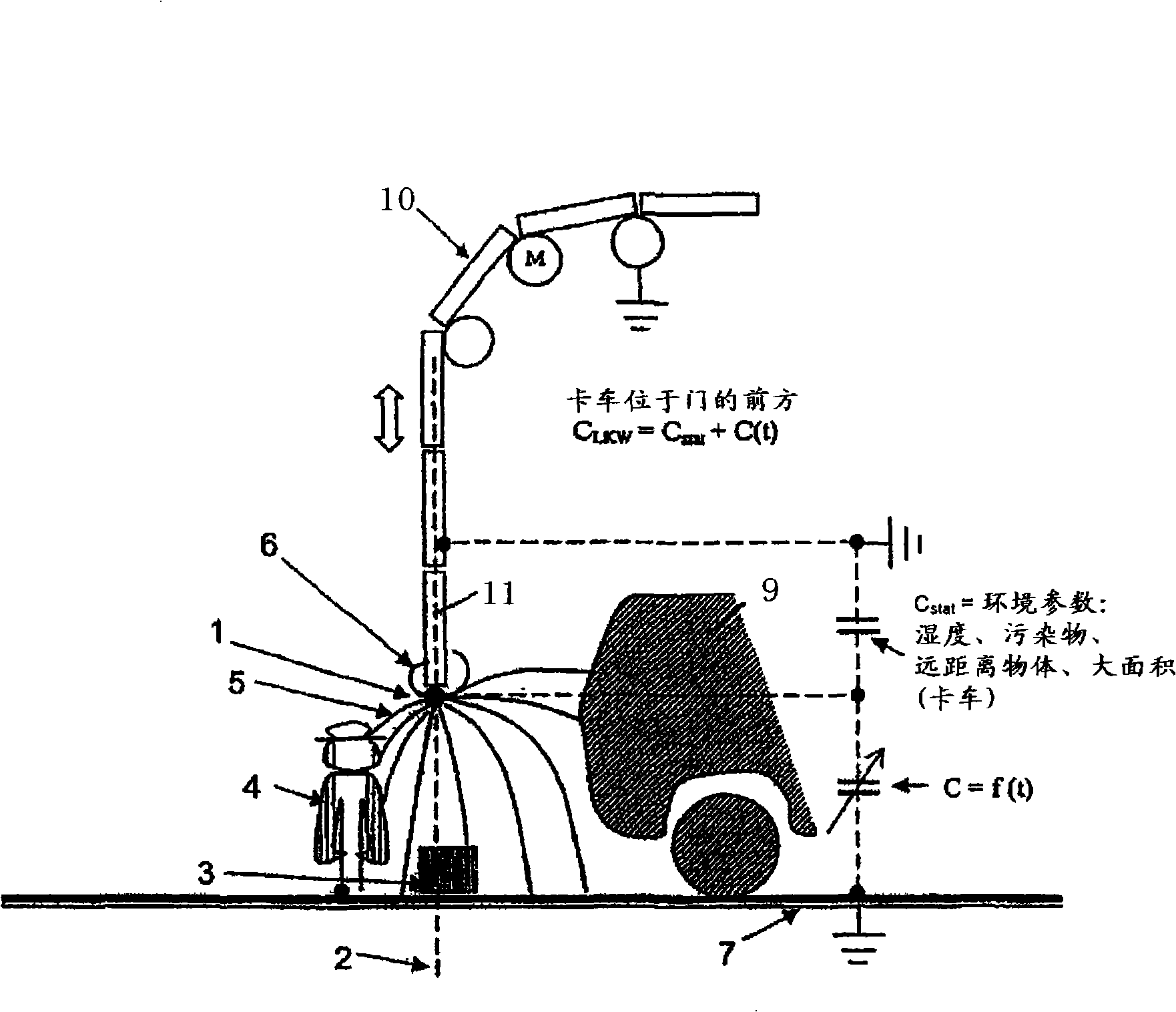
[0016] figure 1 A schematic diagram of the closing process of the rolling door 10 is shown, wherein an obstacle is located in the vicinity of the door closing path 2 . In this embodiment, the door 10 can be moved up and down by means of a door drive. The gate drives are controlled by a controller according to the invention.

[0017] According to the invention, the sensor surface 1 is arranged in an insulating manner at the lowest door panel 11 of the door leaf and during closing the sensor capacitance of said sensor surface is detected with respect to ground potential. In the figure, the field lines of the capacitive sensor are shown as solid lines. On the one hand, the static field lines 6 towards the grounded door panel lead to a constant influence on the capacitance during the door movement. In addition, the static interference capacitance is affected by other parameters of the environment, humidity, pollutants and objects at a distance. In this embodiment, the rear sid...


PUM


Abstract

The present invention relates to a method of controlling a door drive, in particular of a roller door, wherein a capacitive sensor is used for the automatic recognition of obstructions in the region of the door closing path, wherein the recognition of obstructions on the closing of the door takes place by a comparison of the then current change in the capacity of the capacitive sensor with respect to a variable with a reference value or a reference curve. The invention furthermore includes a corresponding system of controlling a door drive.

Description

technical field [0001] The present invention relates to a method and system for controlling a door driver, and more particularly to a method and system for controlling a door driver for a high-speed door, wherein a capacitive sensor is used to automatically identify obstacles near the door closing path. Background technique [0002] Methods are already known in the state of the art in which obstacles are automatically detected and thus the door is automatically stopped so that jamming is prevented. [0003] Light barriers and light curtains for detecting whether people are in the door closing area are often installed in door closing areas such as self-closing elevator doors, revolving doors or leaf doors, and the output signals of the light barriers and light curtains affect the interruption and restart of the closing process Open. Light barriers and light curtains are installed, for example, in door facades, where light release openings and reflective prisms arranged in th...

Claims


Application Information

Patent Timeline
IPC IPC(8): E05F15/20E06B9/56
CPCG05B2219/45242E06B9/88G05B2219/37418E05Y2900/106E05F15/2023H03K17/955E05F15/0073G05B2219/43202E05F15/46E05F15/73E05Y2900/00
Inventor 米夏埃尔·赫尔曼
Owner MARANTEC ANTRIEB STEUERUNG
Why Eureka
Try Eureka