Motor driving apparatus

一种驱动装置、电动机的技术,应用在电路装置、电池电路装置、电动发电机控制等方向,能够解决不能有效利用等问题

Active Publication Date: 2009-04-08
FANUC LTD
View PDF2 Cites 12 Cited by
  • Summary
  • Abstract
  • Description
  • Claims
  • Application Information

AI Technical Summary

Problems solved by technology

[0014] As can be seen from the above, there is the following problem in the motor drive device of the prior art: the electric energy charged in the capacitor cannot be used where it is necessary to provide power to the main motor 4 according to the mechanical requirements, but can be used where it is not needed. , the electric energy charged in the capacitor 6 cannot be effectively used in the motor drive device

Method used


Image

  • Motor driving apparatus
  • Motor driving apparatus
  • Motor driving apparatus

Examples


Embodiment Construction

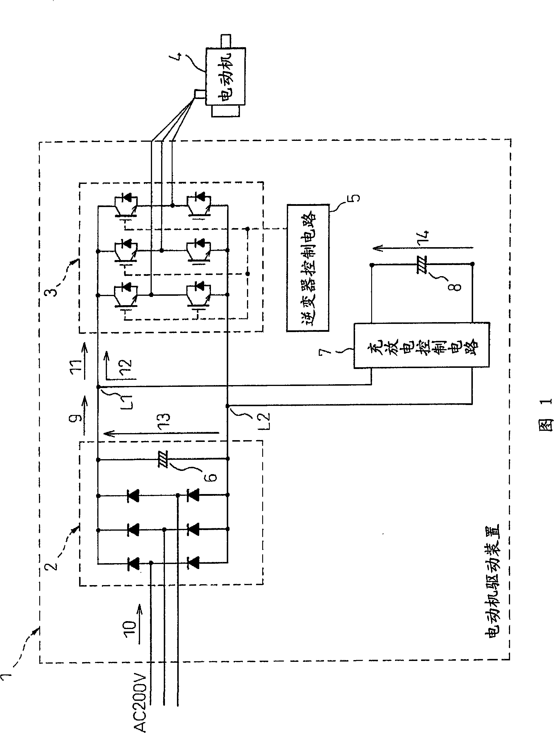
[0043] FIG. 1 is a circuit diagram of a motor drive device according to an embodiment of the present invention. A motor drive device 1 shown in FIG. 1 has a converter 2 , an inverter 3 , a motor 4 , an inverter control circuit 5 , a smoothing capacitor 6 , a charge and discharge control circuit 7 , and a capacitor 8 . In FIG. 1 , 9 denotes a converter output current, 10 denotes a converter input current, 11 denotes a DC link current, 12 denotes a capacitor output current, 13 denotes a DC link voltage, and 14 denotes a capacitor voltage. Regarding marks 10~14, they will be used later Figure 7 The simulation results of the waveforms of each part during the operation of the shown motor drive device 1 will be described.

[0044] AC power is supplied to converter 2 , and converter 2 rectifies and converts AC to DC, and charges capacitor 8 via smoothing capacitor 6 and charge / discharge control circuit 7 . The inverter 3 that performs DC / AC conversion switches the energy charged i...


PUM


Abstract

The invention provides a motor driving apparatus that supplies energy to a motor so that the peak of the input current from a power supply to the motor can also be suppressed when particularly large energy is needed during the second half period of motor acceleration. A motor driving apparatus 1 having a converter 2, which receives AC voltage and converts it to DC power, and an inverter 3, which receives the DC power and converts it to AC power, includes a charge / discharge control circuit 7 and a capacitor 8 connected in parallel to a link section between the converter 2 and the inverter 3, and energy stored in the capacitor C8 is charged and discharged at arbitrary timing by the charge / discharge control circuit 7.

Description

technical field [0001] The present invention relates to a motor drive device, and more particularly to a motor drive device that stores regenerative energy generated during deceleration of a motor in a capacitor and uses it as power running energy during acceleration. Background technique [0002] Fig. 13 is a circuit diagram of a conventional motor drive device. A motor drive device 101 shown in FIG. 13 has a converter 2 , an inverter 3 , a motor 4 , an inverter control circuit 5 , and a smoothing capacitor 6 . In FIG. 13 , 109 denotes a converter output current, 110 denotes a converter input current, 111 denotes a DC link current (DC link current), 112 denotes a capacitor output current, and 113 denotes a DC link voltage (capacitor voltage). Regarding symbols 110~113, use them later Figure 14 The simulation results of the respective waveforms at the time of operation of the motor drive device 101 shown in FIG. 13 will be described. [0003] The AC power is supplied to t...

Claims


Application Information

Patent Timeline
Patent Type & Authority Applications(China)
IPC IPC(8): H02P3/18
CPCH02M3/158H02P27/08H02M5/458H02J7/345
Inventor 松原俊介岩下平辅山田裕一羽生茂树白水雅朋酒井幸次郎
Owner FANUC LTD
Why Eureka
Try Eureka