Tension side-fixing bone plate for olecranon process of ulna

A technology of olecranon and bone plate, applied in the direction of fixator, outer plate, internal bone synthesis, etc., can solve the problems of cumbersome surgery, long time, large trauma, etc., achieve convenient operation, enhance stability, and reduce incidence Effect

Inactive Publication Date: 2009-04-15
张英泽
View PDF0 Cites 11 Cited by
  • Summary
  • Abstract
  • Description
  • Claims
  • Application Information

AI Technical Summary

Problems solved by technology

The main disadvantages of this olecranon plate in use are: first, the steel plate of the bone plate is relatively flat, which does not conform to the ridge-like anatomical shape of the ulnar crest, and can only be placed on the ulnar crest during the implantation of the plate. On one side of the bone surface, the maximum tension side of the ulna is the ulnar crest side, so this kind of fixation belongs to the partial tension side fixation, which makes the tensile strength of the ulna on the opposite side of the plate after the fracture fixation is low, and the fixation is not firm. It conforms to the fracture fixation principle of tension side fixation, which is not conducive to the stability and healing of fractures
Second, the end of the arc-shaped bone plate is not easy to break through the triceps tendon at the olecranon during the implantation process. Part of the triceps tendon needs to be cut off before the end of the olecranon bone plate can be implanted, resulting in The operation is cumbersome, time-consuming, traumatic, and bleeding, and it is not conducive to the recovery of normal elbow extension strength and elbow joint function after the operation

Method used


Image

  • Tension side-fixing bone plate for olecranon process of ulna
  • Tension side-fixing bone plate for olecranon process of ulna
  • Tension side-fixing bone plate for olecranon process of ulna

Examples


Embodiment Construction

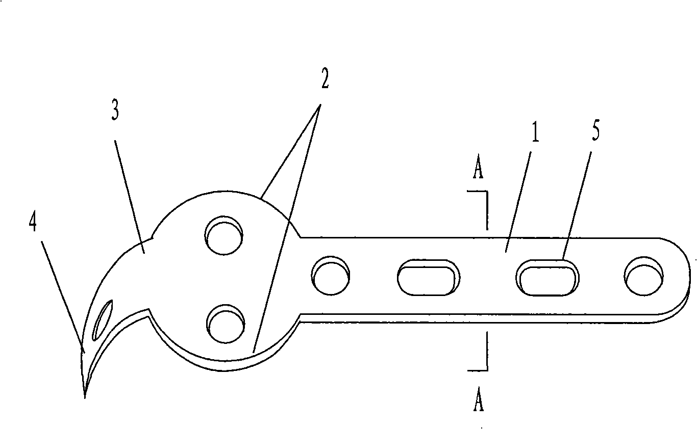
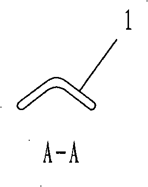
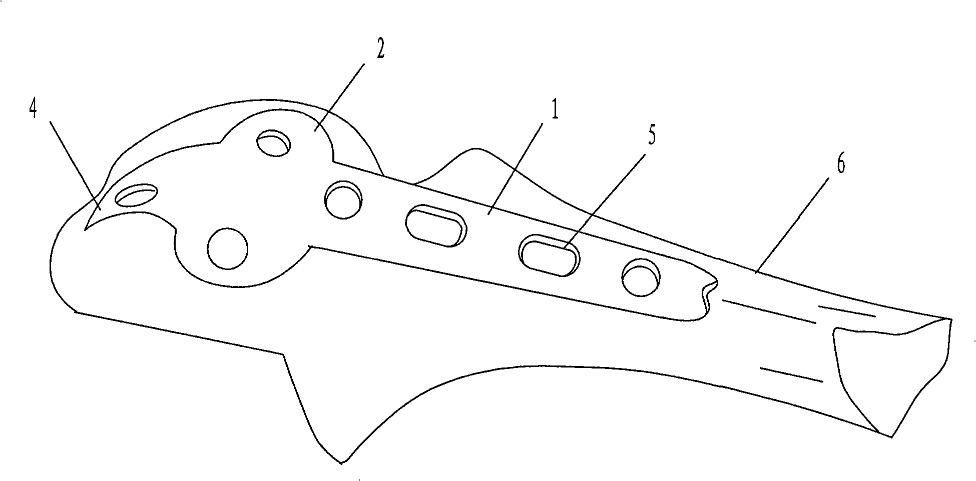
[0015] As shown in the figure, the steel plate body 1 of the olecranon olecranon bone plate of the present invention is designed according to the anatomical shape of the ulnar ridge using an angle steel plate, and the starting point of bending is the lower edge of the semicircular abduction protrusion 2 until the plate body 1, the angle gradually changes from proximal to distal from 110° to 80°, which is consistent with the anatomical shape of the ulnar crest. After adopting this shape, the plate body is covered on the ulnar crest during the operation, and the implanted nail is implanted and fixed, so as to realize the real tension side fixation, enhance the stability of the fracture fixation, and facilitate the healing of the fracture.

[0016] The figure also shows that on the basis of the existing olecranon bone plate, the elbow 3 is changed into a head hook 4 arc-shaped design, so that the arc conforms to the anatomical shape of the normal human olecranon. It is easy to pe...


PUM


Abstract

The invention discloses an olecroanon tension side fixation bone fracture plate, which belongs to the technical field of orthopaedic medical apparatus and aims to provide an olecroanon bone fracture plate which realizes tension side fixation, strengthens the fixing strength and stability of a fracture part and facilitates the healing of fracture. The olecroanon bone fracture plate adopts the following technical proposal: the plate body plate plane of the olecroanon bone fracture plate is of an angle steel plate shape along a longitudinal shaft of a plate body; and the starting point of a bent angle steel plate is the lower edge of a semicircular external spread protrusion part to the rear end of the plate body, and the angle of the bent angle steel plate gradually changes from 110 to 80 degrees from the near end to the far end and corresponds to the anatomic shape of an ulna ridge. The olecroanon bone fracture plate has the advantages that the olecroanon bone fracture plate breakthroughs the planar design concept of the prior bone fracture plate, adopts the angle steel plate plane corresponding to the anatomic shape of the ulna ridge, realizes the real extension side fixation, strengthens the stability of fracture fixation, and facilitates the healing of fracture; besides, the olecroanon bone fracture plate adopts an uncommon proposal, obtains unexpected good effect, and solves the long-standing problem of treatment of the olecroanon fracture.

Description

technical field [0001] The invention relates to a bone plate used for treating olecranon fractures, and belongs to the technical field of orthopedic medical appliances. Background technique [0002] The vast majority of olecranon fractures are intra-articular fractures, and open reduction and internal fixation are required for treatment. The effects that the internal fixation should achieve are firstly accurate reduction and restoration of a smooth articular surface, secondly, the fixation should have sufficient strength, and thirdly, normal elbow extension strength should be restored. [0003] At present, the common internal fixation methods for olecranon fractures include Kirschner wire tension band fixation and plate fixation. Kirschner wire tension band fixation is based on the principle of AO tension band, the variable tension stress is compressive stress, so that the separated olecranon closes up and the fracture end is pressurized. Plate fixation includes reconstruc...

Claims


Application Information

Patent Timeline
Patent Type & Authority Applications(China)
IPC IPC(8): A61B17/80
Inventor 张英泽
Owner 张英泽
Why Eureka
Try Eureka