Method and apparatus for distributing powdery pigment glue
A colorant and powder state technology, which is applied in the field of powder state colorant gluing cloth method and cloth equipment, can solve the problems of screen blockage, low production efficiency, pattern deformation, etc.
- Summary
- Abstract
- Description
- Claims
- Application Information
AI Technical Summary
Problems solved by technology
Method used
Image
Examples
no. 1 example
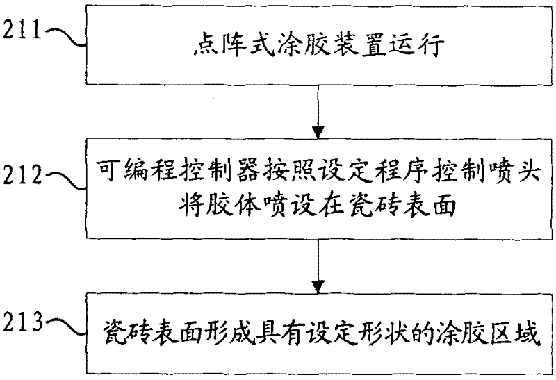
[0066] Figure 7 It is a structural schematic diagram of the first embodiment of the present invention. The dot-matrix gluing device 1' of this embodiment is composed of 5 to 15 nozzle groups 11 arranged in a certain layout, and each nozzle group 11 is composed of 3 to 6 nozzles 10 arranged in a certain layout, and each nozzle 10 is composed of The programming controller is responsible for spraying the colloid on the surface of the ceramic tile 5 and forming an overall dot-matrix sprinkler head layout above the conveying platform 4 . Specifically, such as Figure 7 As shown, the dot-matrix gluing device 1' is composed of 9 nozzle groups 11 arranged in sequence along the vertical direction of the tile conveying direction A, and each nozzle group 11 is composed of 4 nozzles 10 arranged in sequence along the tile conveying direction A, A 36-dot matrix dot-matrix nozzle layout is formed. Each shower head 10 is connected with a programmable controller, and the programmable contr...
no. 2 example
[0069] Figure 12 It is a structural schematic diagram of the second embodiment of the present invention. The dot-matrix gluing device of this embodiment includes one or more horizontal shafts 12 and one or more nozzle groups 11, the horizontal shafts 12 are set to be perpendicular to the tile conveying direction A, and the nozzle groups 11 are connected to the horizontal shaft 12 by transmission. The nozzle group 11 can move left and right along the direction B on the horizontal axis 12. Whether it moves or not, the moving speed and the moving time are controlled by the programmable controller. Each nozzle 10 in the nozzle group 11 is also controlled by the programmable controller. Colloid is sprayed on the surface, and a horizontally moving dot-matrix nozzle layout is formed above the conveying platform 4 . This embodiment is basically the same as the first embodiment in terms of nozzle group, nozzle structure, function and working process, etc. The difference lies in the w...
no. 3 example
[0071] Figure 13 It is a structural schematic diagram of the third embodiment of the present invention. The dot-matrix gluing device in this embodiment includes one or more longitudinal axes 13 and one or more nozzle groups 11, the longitudinal axes 13 are arranged parallel to the tile conveying direction A, and the nozzle groups 11 are connected to the longitudinal axis 13 by transmission. The nozzle group 11 can move back and forth along the direction A on the longitudinal axis 13, and whether it moves or not, the moving speed and the moving time are controlled by the programmable controller, and each nozzle 10 in the nozzle group 11 is also controlled by the programmable controller. Colloid is sprayed on the surface, and a vertically moving dot-matrix nozzle layout is formed above the conveying platform 4 . This embodiment is basically the same as the technical solution of the first embodiment in terms of nozzle group, nozzle structure, function and working process, etc. ...
PUM
 Abstract
Description
Claims
Application Information
 - R&D
- Intellectual Property
- Life Sciences
- Materials
- Tech Scout
- Unparalleled Data Quality
- Higher Quality Content
- 60% Fewer Hallucinations
Browse by: Latest US Patents, China's latest patents, Technical Efficacy Thesaurus, Application Domain, Technology Topic, Popular Technical Reports.
© 2025 PatSnap. All rights reserved.Legal|Privacy policy|Modern Slavery Act Transparency Statement|Sitemap|About US| Contact US: help@patsnap.com


