Distributed layer-dividing grade temperature error compensating method of optical fiber gyroscope

A fiber optic gyroscope, temperature error technology, applied in Sagnac effect gyroscopes, thermometers, thermometers with physical/chemical changes, etc., can solve poor model accuracy, temperature field analysis of fiber optic gyroscopes, and ignore other important Links and other issues to achieve the effect of ensuring truthfulness and comprehensiveness and improving accuracy

Active Publication Date: 2009-04-15
BEIJING AEROSPACE TIMES OPTICAL ELECTRONICS TECH
View PDF1 Cites 35 Cited by
  • Summary
  • Abstract
  • Description
  • Claims
  • Application Information

AI Technical Summary

Problems solved by technology

Due to the instability and time-varying nature of the fiber optic gyroscope with temperature changes, if the usual time series and other parameter identification-based techniques are used, the accuracy of the model will be poor and the compensation effect will not be ideal.
Moreover, the temperature models of most fiber optic gyroscopes are limited to static temperature models or simplified dynamic temperature models established by local temperature monitoring, which are far from meeting the performance requirements of high-precision fiber optic gyroscopes under temperature changes in engineering applications. Stability and Consistency
[0003] The main problems in the current temperature model of the fiber optic gyroscope are: no systematic and comprehensive analysis of the temperature field of the fiber optic gyroscope, no analysis of all optical components, and no selection principles for setting temperature monitoring points. Focusing on

Method used


Image

  • Distributed layer-dividing grade temperature error compensating method of optical fiber gyroscope
  • Distributed layer-dividing grade temperature error compensating method of optical fiber gyroscope
  • Distributed layer-dividing grade temperature error compensating method of optical fiber gyroscope

Examples


Embodiment Construction

[0046] The method of the present invention will be described in detail below in combination with specific embodiments.

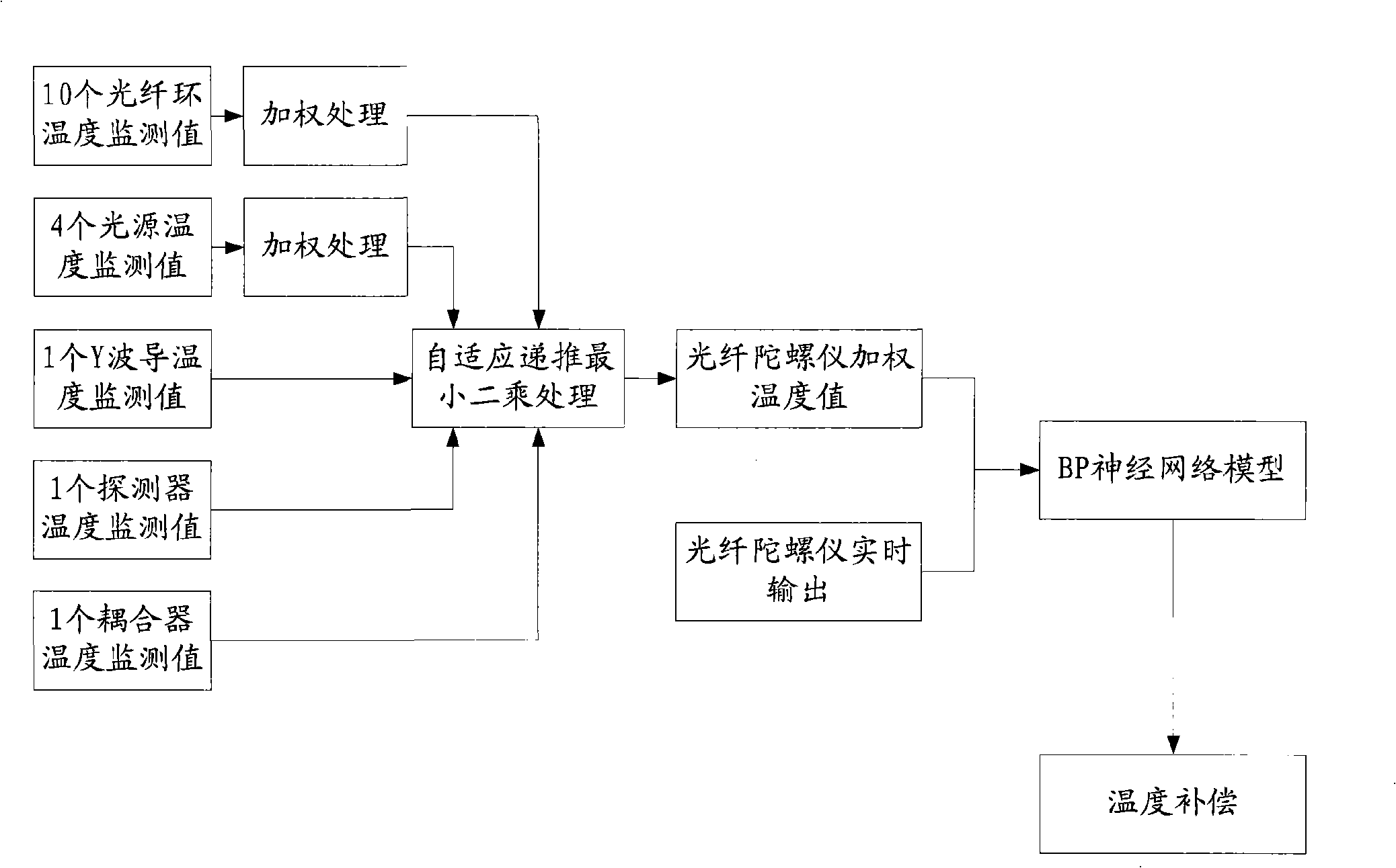
[0047] Such as figure 1 , 2 As shown, the steps of a distributed hierarchical temperature error compensation method for an optical fiber gyroscope in the present invention are as follows:

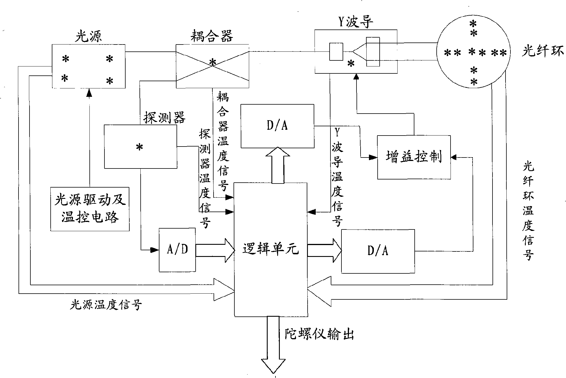
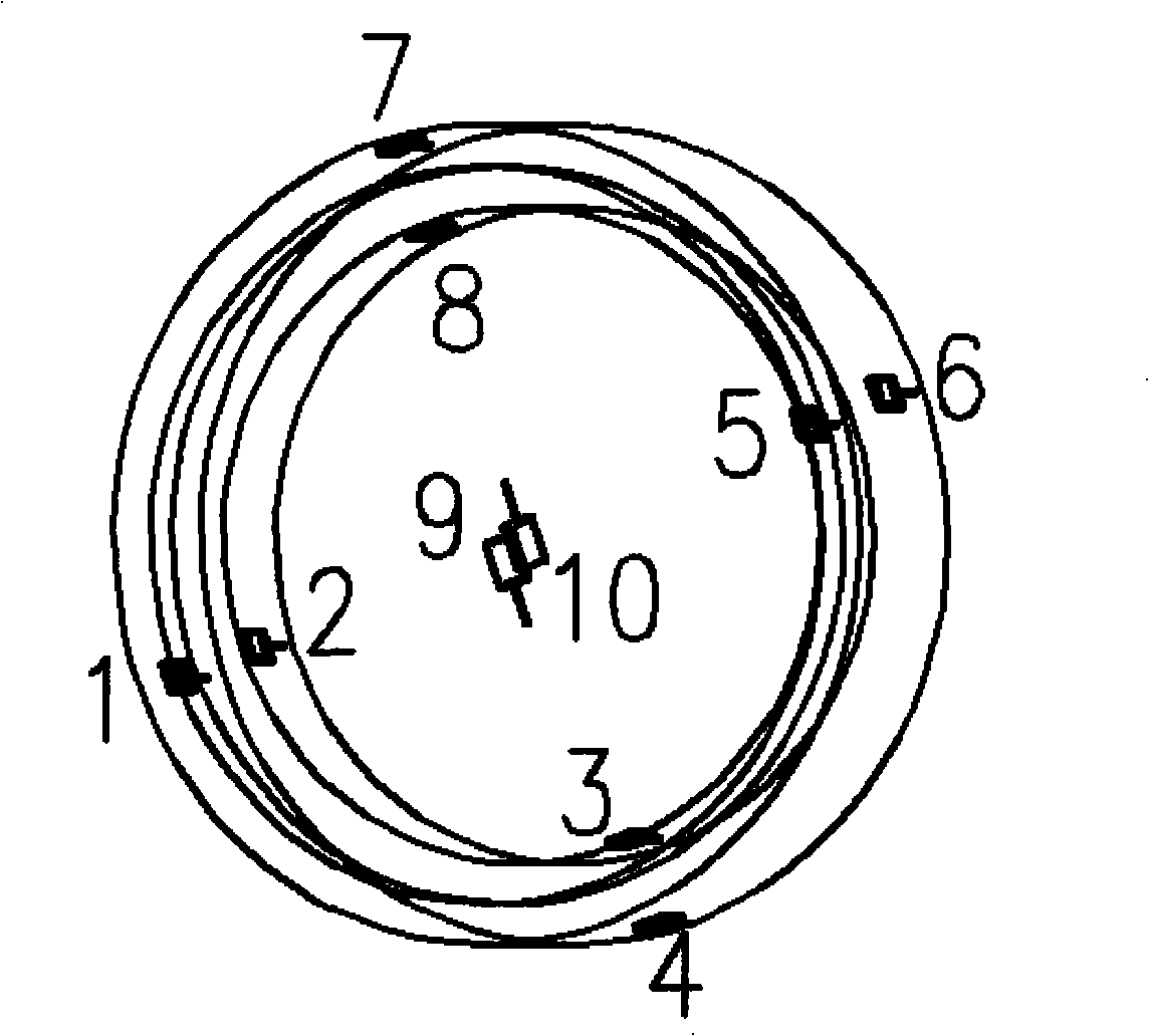
[0048] (1) Take the five optical components of optical fiber ring, light source, Y waveguide, detector and coupler as temperature monitoring objects, and determine the number and distribution of temperature monitoring points for each optical component;

[0049] The number of temperature monitoring points required by the fiber optic ring can be obtained by using formula (1):

[0050] n = Δ · ( L · D · ( λ α ) ...


PUM


Abstract

An optical fibre gyroscope distributed layered temperature error compensation method comprises the following steps: (1) five optical components of a fiber-optic ring, a light source, a Y wave guide, a detector and a coupler are taken as temperature monitoring objects for determining the number of the temperature monitoring points of each optical component and the distributing form; (2) self-adapting recurrence and least squares treatment are carried out on monitoring value of each temperature monitoring point for obtaining temperature output value of the optical fibre gyroscope; (3) a neural network model is built for obtaining temperature drift compensation value by utilizing the temperature output value and the real time outputting data of the optical fibre gyroscope; (4) the real time outputting data of the optical fibre gyroscope minus the temperature drift compensation value means temperature compensation of the optical fibre gyroscope. The method can overcome the disadvantages of the prior art and reflect the temperature field inside the optical fibre gyroscope systematically and in an all-round way, and has significance in the performance research and improvement under the condition of the temperature environment of the optical fibre gyroscope.

Description

technical field [0001] The invention relates to a temperature compensation method of an optical fiber gyroscope. Background technique [0002] Temperature has a great influence on the performance of fiber optic gyroscopes, especially high-precision fiber optic gyroscopes. The temperature change comes from the fiber optic gyroscope's own heating and environmental temperature changes. Due to the non-stationarity and time-varying nature of the fiber optic gyroscope with the change of temperature, if the technology based on parameter identification such as the usual time series is used, the accuracy of the model will be poor, and the compensation effect will not be ideal. Moreover, the temperature models of most fiber optic gyroscopes are limited to static temperature models or simplified dynamic temperature models established by local temperature monitoring, which are far from meeting the performance requirements of high-precision fiber optic gyroscopes under temperature change...

Claims


Application Information

Patent Timeline
IPC IPC(8): G01C19/72G01C25/00G01K11/32
Inventor 黄磊王巍于海成彭秋芫
Owner BEIJING AEROSPACE TIMES OPTICAL ELECTRONICS TECH
Why Eureka
Try Eureka