Method and apparatus for movement planning of apery robot ankle

A humanoid robot and motion planning technology, applied in two-dimensional position/channel control, road network navigator, etc., can solve problems affecting the stability of the robot's landing process, increase flexibility, reduce reaction force, and improve stability sexual effect

Active Publication Date: 2009-04-15
BEIJING INSTITUTE OF TECHNOLOGYGY
View PDF0 Cites 5 Cited by
  • Summary
  • Abstract
  • Description
  • Claims
  • Application Information

AI Technical Summary

Problems solved by technology

According to the existing planning method, when the non-supporting foot of the humanoid robot lands in advance, it will rush to the ground at a certain speed, and the ground will give it a reaction force, which will inevitably affect the stability of the robot's landing process.

Method used


Image

  • Method and apparatus for movement planning of apery robot ankle
  • Method and apparatus for movement planning of apery robot ankle
  • Method and apparatus for movement planning of apery robot ankle

Examples


Embodiment 1

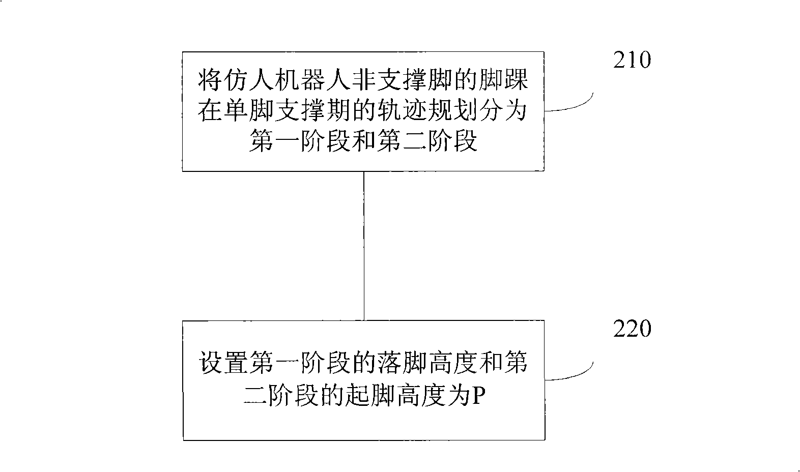
[0030] Embodiments of the present invention provide a motion planning method for the ankle of a humanoid robot, such as figure 2 shown, including the following steps:

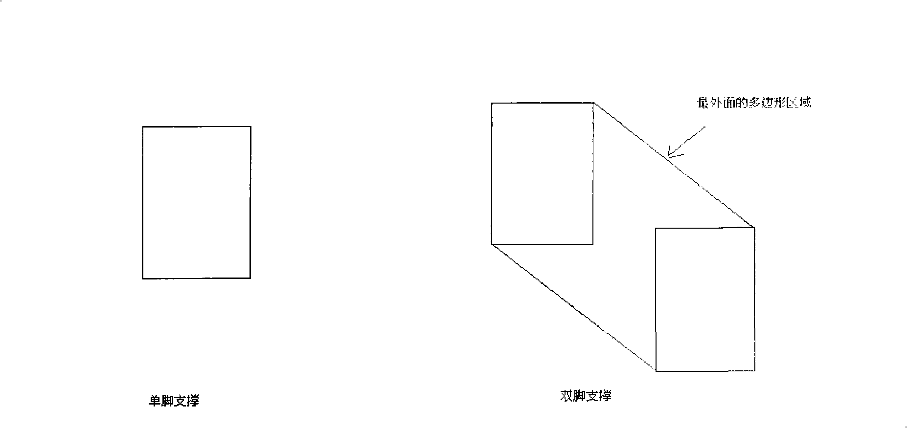
[0031] 210: The trajectory planning of the ankle of the non-supporting foot of a humanoid robot in the single-foot support period is divided into the first stage and the second stage.

[0032] In each of the above-mentioned stages, three key points are respectively included: starting point, middle point, and foothold point. The trajectory planning of the ankle of the non-supporting foot of the humanoid robot in the single-foot support period is based on the above three key points. on the planning.

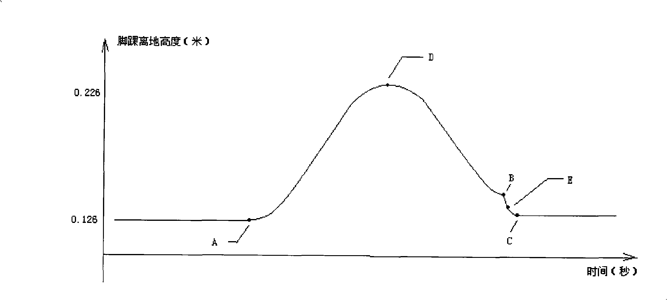
[0033] 220: Set the landing height of the first stage and the kicking height of the second stage as P, where P=L+F, L is the distance between the ankle and the instep, F is the compensation for the height of the ankle from the ground, and L>0, F >0.

[0034] Set the landing height of the first stage and the star...

Embodiment 2

[0040] An embodiment of the present invention provides a motion planning device for a humanoid robot ankle, such as Figure 5 shown, including:

[0041] The phase division module 501 is used to divide the trajectory planning of the ankle of the non-supporting foot of the humanoid robot into the first phase and the second phase during the single-foot support phase.

[0042] The setting module 502 is used to set the landing height of the first stage and the kicking height of the second stage as P, wherein P=L+F, L is the distance between the ankle and the instep, F is the amount of compensation for the height of the ankle from the ground, and L >0, F>0.

[0043] The setting module 502 sets the height of the feet in the first stage and the height of the feet in the second stage to the same value P, that is, L is the distance between the ankle and the instep, F is the compensation for the height of the ankle from the ground, and L>0, F >0.

[0044] The setting module 502 sets t...


PUM


Abstract

The invention discloses a movement planning method and a device of ankles of a humanoid robot, belonging to the technical field of humanoid robot movement planning. The method comprises: the trail planning of the ankles of non-supporting feet of the humanoid robot is divided into a first period and a second period in the period of odd-leg supporting; setting the stamping height in the first period and the jumping height in the second period as P. The device comprises: a phasing module used for dividing the trail planning of the ankles of non-supporting feet of the humanoid robot into the first period and the second period in the period of odd-leg supporting; a setting module used for setting the stamping height in the first period and the jumping height in the second period as P; wherein, is equal to L plus F, L is a distance between the ankle and feet surface, and F is the ground clearance compensation of ankles, and L is more than 0 and F is more that 0. In the invention, the trail planning of the ankles of non-supporting feet of the humanoid robot is divided into the first period and the second period in the period of odd-leg supporting, and counterforce of the ground to the feet surface of the robot is decreased at the moment when the feet surface of the humanoid robot stamps the ground in the process of action performance, thus increasing the flexibility of stamping the ground of the feet surface of the humanoid robot and improving the stability.

Description

technical field [0001] The invention relates to the technical field of humanoid robot motion planning, in particular to a motion planning method and device for the ankle of a humanoid robot. Background technique [0002] Motion planning of humanoid robot is a very important field in humanoid robot research. The action performance of the humanoid robot is realized by the rotation of the motors distributed on each joint of the humanoid robot. The number of motors for each joint represents the number of degrees of freedom on the joint. How each motor rotates at each moment is given by motion planning before the action performance of the humanoid robot. At present, the method of humanoid robot motion planning is mainly based on the stability principle of zero moment point (ZMP, ZeroMoment Point). The method is to set the trajectory of the ankle joint of the foot according to the ground environment first. Find the torso trajectory with the maximum stability margin as the final...

Claims


Application Information

Patent Timeline
Patent Type & Authority Applications(China)
IPC IPC(8): G01C21/34G05D1/02
Inventor 黄强许威李月李敬刘嘉宇
Owner BEIJING INSTITUTE OF TECHNOLOGYGY
Why Eureka
Try Eureka