
Magnifying glass with illuminating effect mounted on small-sized electric appliance and application thereof

A lighting effect and magnifying glass technology, applied in magnifying glass, telephone structure, instruments, etc., can solve the problems of not being able to meet the needs of material and cultural life, not being able to enhance reading for the elderly, not being able to achieve magnification, etc., to achieve increased additional use value and portability Good effect with good applicability

Inactive Publication Date: 2011-07-06
惠州德赛信息科技有限公司
View PDF3 Cites 1 Cited by
  • Summary
  • Abstract
  • Description
  • Claims
  • Application Information

AI Technical Summary

Problems solved by technology

The technical purpose of these magnifying glass structures is to see the relevant information of the mobile phone itself and has no other purpose. Due to the limitation of its setting structure, it is extremely inconvenient to use these magnifying glasses installed on the mobile phone to magnify other items, and even some structures cannot Realize zooming in on objects other than the phone itself
Thereby the structure of these magnifying glasses can not effectively assist the elderly to enhance reading (as reading and reading newspapers) ability
In addition, many existing mobile phones are equipped with luminous lights or torches for camera, and these luminous lights or torches are installed vertically on the back wall of the mobile phone, and their functions are relatively single, only for vertical lighting.
Therefore, in the prior art, the structure of the magnifying glass with lighting effects installed on small electrical appliances has not been disclosed, thus it cannot meet people's increasing material and cultural life needs.

Method used


Image

  • Magnifying glass with illuminating effect mounted on small-sized electric appliance and application thereof
  • Magnifying glass with illuminating effect mounted on small-sized electric appliance and application thereof
  • Magnifying glass with illuminating effect mounted on small-sized electric appliance and application thereof

Examples


Embodiment 1

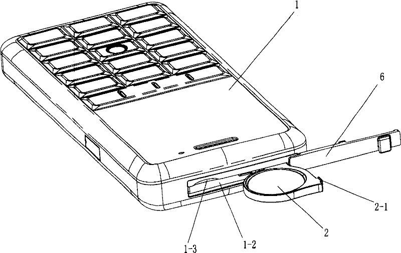
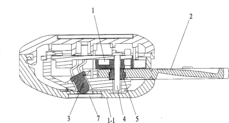
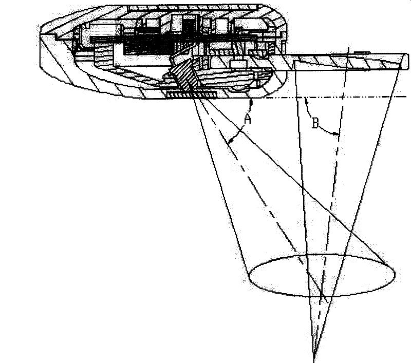
[0030] figure 1 — Figure 4 A specific structure of the present invention is shown, by figure 1 — Figure 4 It can be seen that the structure of the magnifying glass includes a mobile phone 1, a magnifying glass 2, and a light-emitting part 3. The light-emitting part 3 is connected to the power supply of the mobile phone 1 and is inclined relative to the back wall surface 1-1 of the mobile phone 1. The numerical range of the inclination angle A is 45° —90°, such as figure 2 Shown; The eyeglass of described magnifying glass 2 is also set to be inclined certain angle relative to the back wall surface 1-1 of described mobile phone 1, and described angle is the clip between the central axis of lens focusing direction and the wall surface 1-1 of mobile phone 1 Angle B, the numerical range of the included angle B is 75°-85°, so that the focus area of ​​the magnifying glass 2 falls into the irradiation area of ​​the luminous element 3 (see image 3 ).

[0031] The magnifying gl...

Embodiment 2

[0035] This embodiment is the same as Embodiment 1 except for the following features: in order to take out the magnifying glass more conveniently, an elastic member can also be provided at the position where the magnifying glass is close to the hinge, and a snap-in structure is set on the magnifying glass; The structure clamps the magnifying glass in the cavity of the small electrical appliance. If you need to use the magnifying glass, press to open the clamping structure, and the magnifying glass will pop out under the elastic force of the elastic part, and you can use it normally. After use, overcome the elastic force to rotate and close the magnifying glass , and then use the clamping structure to clamp it tightly.

Embodiment 3

[0037] This embodiment is the same as Embodiment 1 except for the following features: the magnifying glass and the mobile phone are hinged through a hinge shaft integrated with the end of the magnifying glass.


PUM


Abstract

The invention discloses a magnifier structure which is arranged on a small electric appliance and has illumination effect. The magnifier structure comprises a small electric appliance, a magnifier and an illumination element; the magnifier is articulated with the small electric appliance, the illumination element is arranged obliquely relative to the wall surface of the small electric appliance, and is connected with a power source of the small electric appliance, and the focal region of the magnifier falls into a illumination region of the illumination element. The magnifier structure can beapplied to a plurality of handheld small electric appliances such as cell phones, remote controllers of various household appliances, radios, MP3, MP4, handheld game players and the like. The magnifier structure has simple and reasonable structure, flexible and convenient use, is applicable to various light conditions, can effectively assist in watching by magnifying, and has a plurality of use forms and wide application range.

Description

technical field [0001] The invention relates to a magnifying display structure, in particular to a magnifying glass structure with lighting effect installed on a small electric appliance. Background technique [0002] With the improvement of living standards, the problem of population aging has appeared all over the world. With the increase of age, the eyesight of human beings generally decreases. In the case of weak ambient light, it is still very difficult to read books and newspapers with the help of a magnifying glass. On the other hand, in the currently commonly used hand-held small electrical appliances, such as mobile phones, remote controls, and radios, there is no relevant structure that is provided with auxiliary amplification to read external information; Mobile phones, such as the Chinese Utility Model Patent No. 200320120653, which discloses "a mobile phone with a magnifying glass"; the Chinese Utility Model Patent No. 200720146864, which discloses "a mobile ph...

Claims


Application Information

Patent Timeline
Patent Type & Authority Patents(China)
IPC IPC(8): G02B25/00H04M1/21
Inventor 周保青曾键黄勇卫道勇
Owner 惠州德赛信息科技有限公司
Learn More