
Ice-melting method suitable for transmission line with multiple fission conductor

A technology of transmission lines and ice-melting methods, which is applied in the installation of overhead lines/cable equipment, electrical components, cables, etc., can solve the problems of substation occupation area and project investment increase, regional power grid impact, power grid decoupling, etc., to achieve Conducive to remote control and monitoring, low project investment costs and high reliability

Active Publication Date: 2009-04-15
NORTHWEST ELECTRIC POWER DESIGN INST OF CHINA POWER ENG CONSULTING GROUP
View PDF0 Cites 15 Cited by
  • Summary
  • Abstract
  • Description
  • Claims
  • Application Information

AI Technical Summary

Problems solved by technology

However, the above methods all have certain operational difficulties in actual operation. For example, in method 1, because the ice-covered line is in an overload operation state, if the circuit is shut down due to a sudden failure, it will have a great impact on the regional power grid, and even Disconnection of the power grid; Method 2 will result in a large increase in substation area and project investment; Method 3 requires a large number of mobile DC ice-melting power supplies

Method used


Image

  • Ice-melting method suitable for transmission line with multiple fission conductor
  • Ice-melting method suitable for transmission line with multiple fission conductor
  • Ice-melting method suitable for transmission line with multiple fission conductor

Examples


Embodiment Construction

[0025] The present invention will be further described in detail below in conjunction with the accompanying drawings.

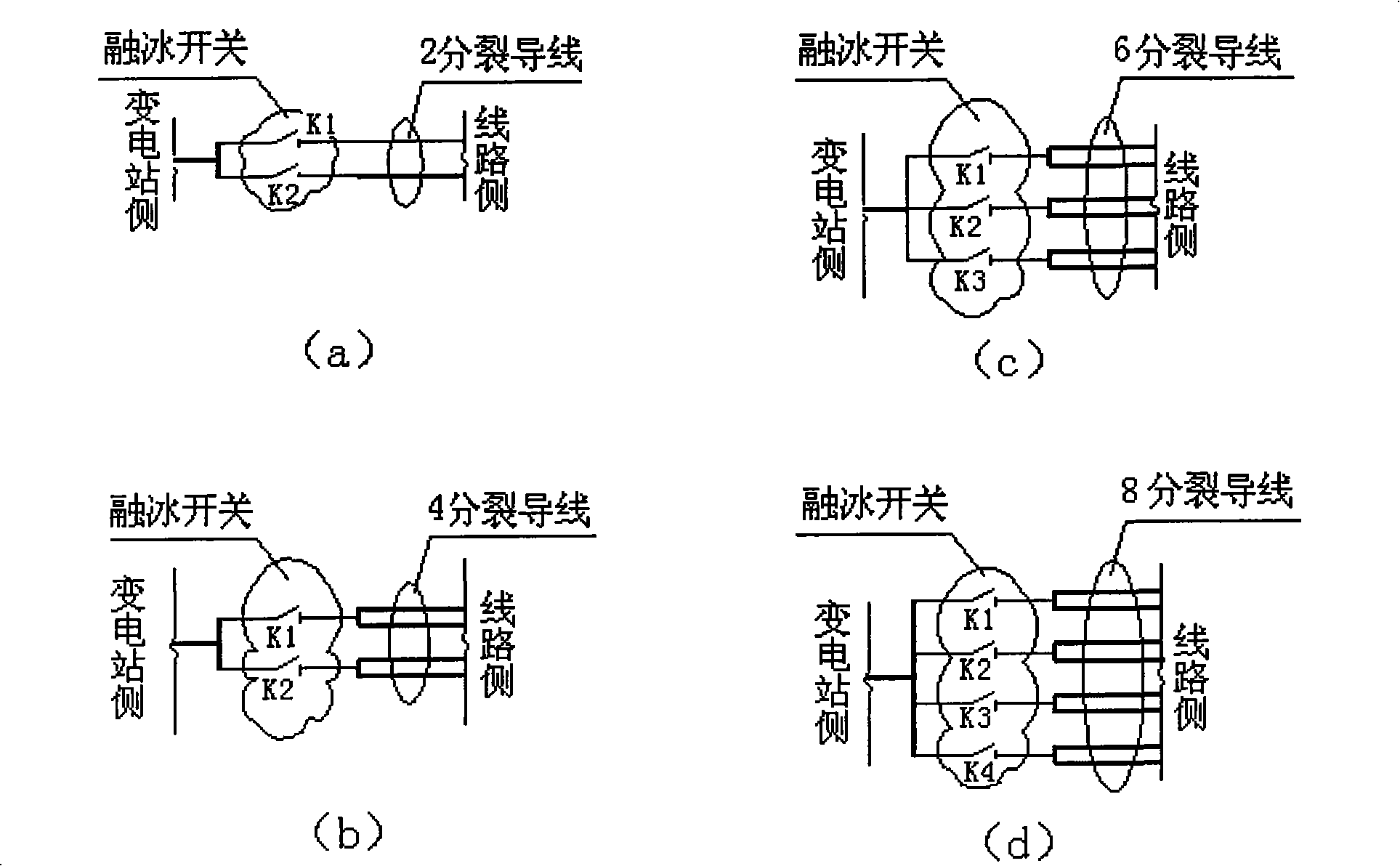
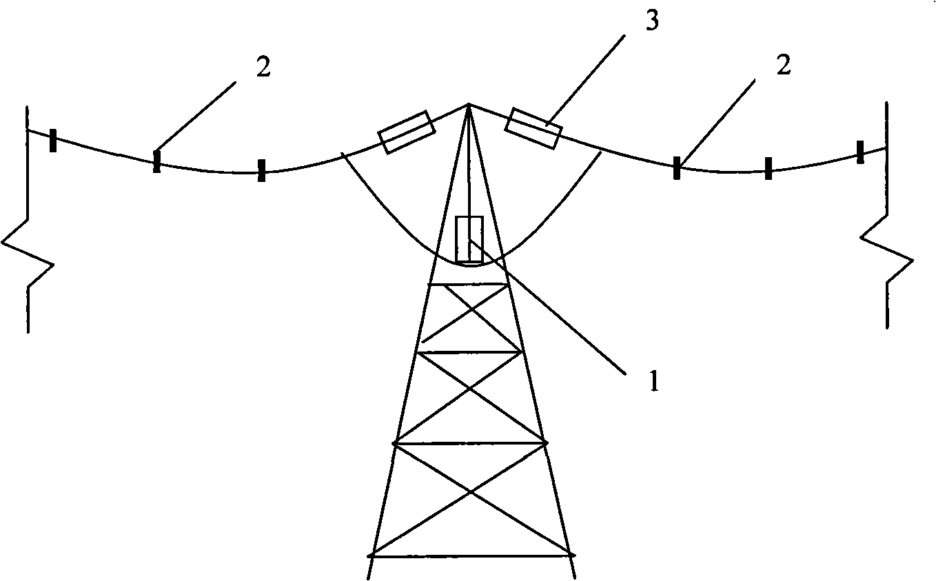
[0026] Such as figure 1 As shown, the installation position of the ice-melting switch arranged on the multi-split conductor is at the junction of the substation (converter station) and the transmission line. In the case of ice-covered wires, by disconnecting several split wires, the current density in the remaining wires that are still connected can be increased, and the heating value of the wires can be increased to melt the ice. In order to reduce the number of ice-melting switches and prevent wires from The setting method of the melting ice switch for instantaneous galloping and multi-split conductors is as follows:

[0027] 1) Double-split wires: each wire is equipped with a melting switch, and a total of two K1 and K2 are installed, see figure 1 (a);

[0028] 2) Four-split wires: install one ice-melting switch on every two wires, and install two K1 an...


PUM


Abstract

The invention discloses a sleet melting method suitable for a power transmission line with multiple bundled conductors. The method comprises the following steps: (1). 2-4 sleet melting switches controlled by an electric operating mechanism are arranged at the connection places between a transformer station or a converter station and the power transmission line with the multiple bundled conductors; (2). suspension string insulation, tension string insulation, mid span and jumper insulation are adopted at the power transmission line side to insulate all sub-conductors of the bundle conductors; (3). when the conductors are covered by ice, one or more sleet melting switches are switched off to disconnect the bundled conductors communicated with the sleet melting switches, thus improving the current density of the communicated multiple bundled conductors and improving the calorific value of the communicated conductors to melt ice; and (4). the step (3) is repeated in the same manner to melt ice covering the bundled conductors. By the method, the sleet melting device has the advantages of simple structure, high reliability, and low investment cost; the normal operation mode of the power transmission line is switched to the sleet melting mode in a simple, safe and reliable manner, which has rare impact on the normal operation of a power grid.

Description

technical field [0001] The invention relates to a method for melting ice of a power transmission line suitable for multi-split conductors. Background technique [0002] In order to effectively melt the ice on the transmission line, there are usually three methods that can be used: one is to increase the current density of the conductor and increase the heating power of the conductor to melt the ice. For example, in a conventional AC substation, several The power on the return line is transferred to the transmission line with serious ice-covering, and the power of the return line is increased to melt the ice; the second is to adopt the method of setting a fixed DC ice-melting power supply in the hub substation, which is suitable for transmission lines with long distances. High-voltage and ultra-high-voltage transmission lines; the third is to adopt the method of setting up a mobile DC ice-melting power supply, which is mainly used for 110kV and below transmission lines with s...

Claims


Application Information

Patent Timeline
Patent Type & Authority Applications(China)
IPC IPC(8): H02G7/16H02G1/02
Inventor 胡明王黎彦申卫华张芳杰钟西岳席晓丽
Owner NORTHWEST ELECTRIC POWER DESIGN INST OF CHINA POWER ENG CONSULTING GROUP
Learn More