Ultrasonic probe inside vagina with changeable detection direction and device

An ultrasonic probe and vaginal technology, applied in catheters, surgery, etc., can solve the problems of not being able to freely control and change the detection direction, unfavorable and flexible detection and observation, etc., to improve the efficiency and accuracy of operations, expand the scope of clinical use, and have good positioning Effect

Active Publication Date: 2009-04-22
河南方正医用电子有限公司
View PDF2 Cites 9 Cited by
  • Summary
  • Abstract
  • Description
  • Claims
  • Application Information

AI Technical Summary

Problems solved by technology

[0003] The present invention overcomes the defect that the probe body of the existing ultrasonic probe cannot be freely controlled to change the detection direction, which is not conducive to flexible detection and observation during surgery, and designs and manufactures an intravaginal ultrasonic probe and device that can change the detection direction

Method used


Image

  • Ultrasonic probe inside vagina with changeable detection direction and device
  • Ultrasonic probe inside vagina with changeable detection direction and device
  • Ultrasonic probe inside vagina with changeable detection direction and device

Examples


Embodiment 1

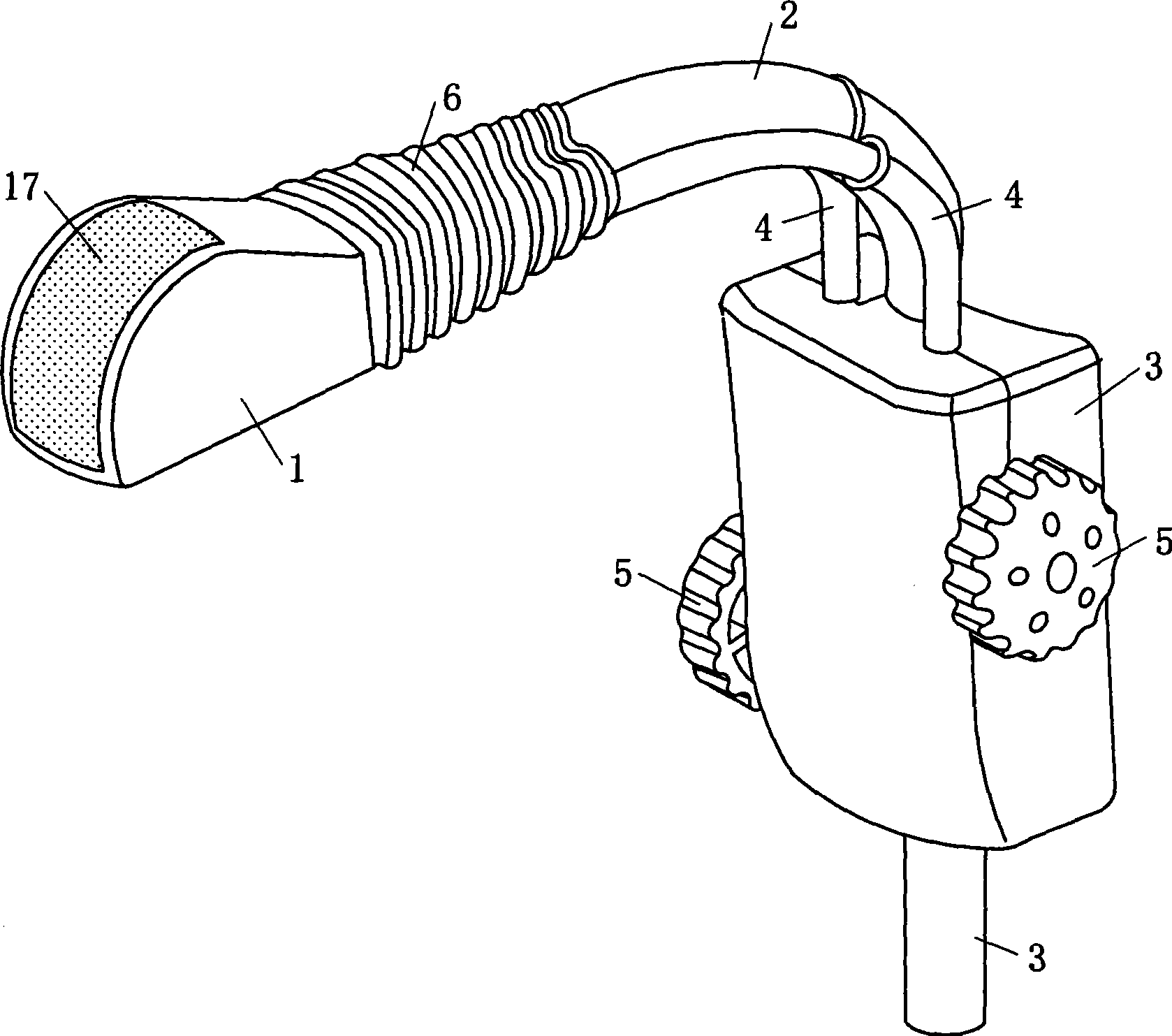
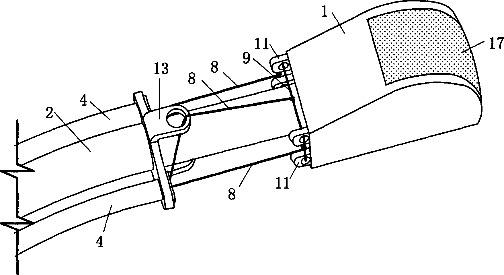
[0037] Embodiment one: see figure 1 , figure 2 , image 3 , an intravaginal ultrasonic probe whose detection direction can be changed, comprising a probe body 1 composed of an ultrasonic sensor 17 and its casing, a cable 2 connected to the ultrasonic sensor 17, and a section at the connection between the probe body casing 1 and the cable 2 The free swing section 6 is provided with a control mechanism 3 for controlling the rotation of the probe body 1 at the other end of the cable 2 .

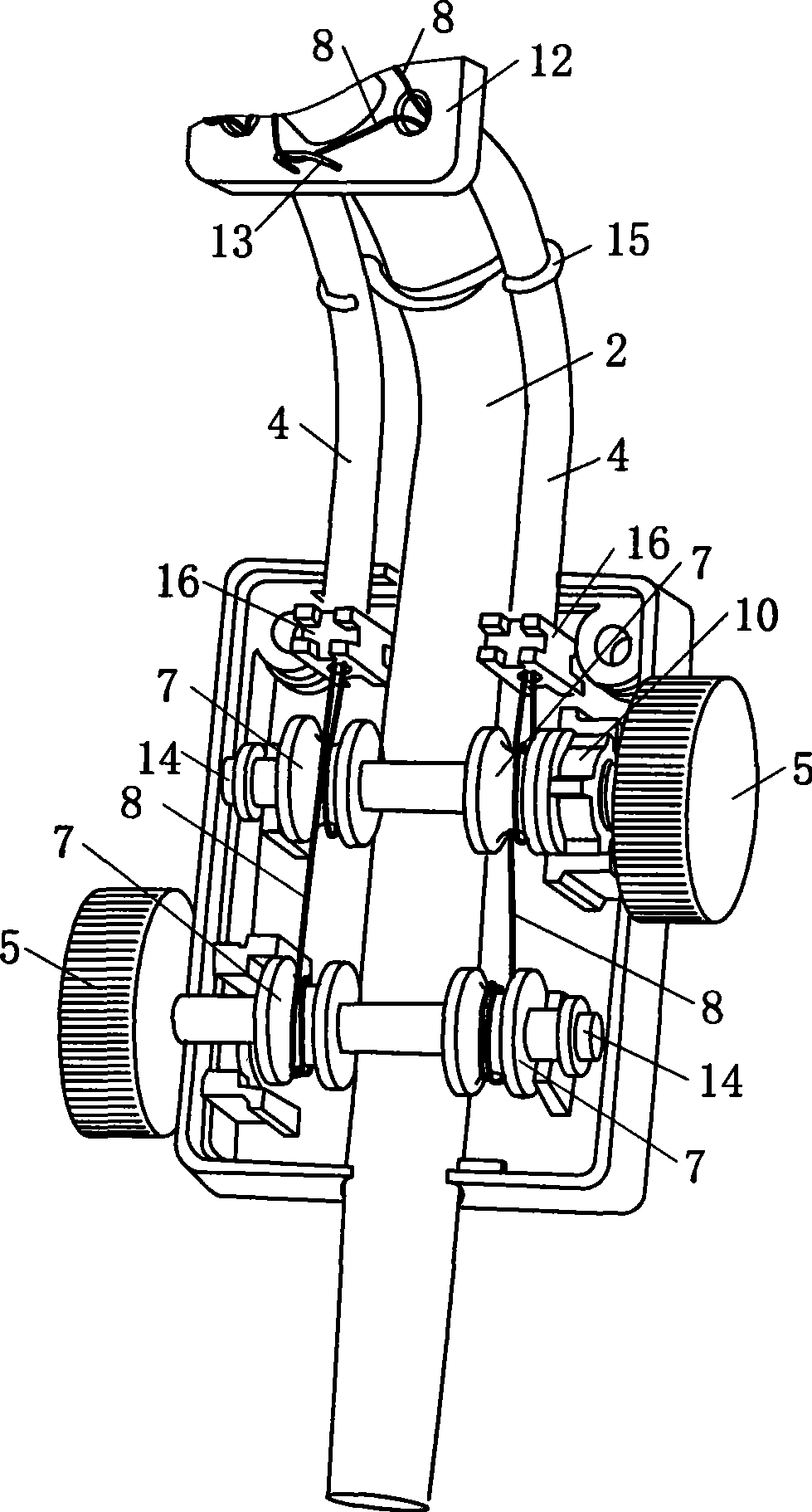
[0038]The free swing section 6 includes a stationary end plate 12 fixed on the cable 2 , and a guide control tube 4 is fixedly connected to the left and right sides of the cable 2 between the stationary end plate 12 and the control mechanism 3 . Two parallel rotating shafts 14 are horizontally installed in the control mechanism 3, and one of the rotating shafts controls left and right swings, and a rotating wheel 7 is respectively installed on the left and right sides of the shaft, respective...

Embodiment 2

[0042] Embodiment two: see Figure 4 , Figure 5 ,Image 6, Figure 7 , an intravaginal ultrasonic device that includes the ultrasonic probe described in Embodiment 1, whose detection direction can be changed. The ultrasonic probe is placed under the lower lobe or above the upper lobe of the vaginal speculum 18 for matching use. There is a certain swing range, and a V-shaped divergent opening 20 matching the probe body 1 shell and the free swing section 6 of the ultrasonic probe is provided on the lower or upper lobe of the vaginal speculum.

[0043] The lower leaf of the vaginal speculum is provided with a groove 19 (Fig. 6) or a through hole 21 (Fig. 6) punched upwards ( Figure 7 ) so as to match with the free swing section 6 and the cable wire 2; match. In order to match with the cover of the free swing section 6 and the cable 2 or its shell.

Embodiment 3

[0044] Embodiment three: see Figure 8 , Figure 9-1 , the numbering is the same as that of Embodiment 1, and the similarities will not be repeated. The difference is that two parallel turntables 23, 24 are vertically installed in the control mechanism 3, and the two sides of the circumference of the upper turntable 23 are wound and fixed. Two connected or separated tie bars 8, the upper ends of the two tie bars respectively pass through the guide control tube 4 and are fixed with the pulling parts of the swing mechanism (such as upper, lower or left and right lugs), and the two sides of the circumference of the lower turntable 24 are wound and fixed. A connected or separated tie bar 8, the upper ends of the two tie bars respectively pass through the guide control tube 4 and are fixed to the pulling part of the swing mechanism. A step mechanism 10 is respectively arranged on the two turntables. The two rotating disks 23, 24 are fixed together with their rotating shafts respe...


PUM


Abstract

The invention relates to a gynaecologic ultrasonic probe capable of changing the direction of a probe body, which comprises the probe body which consists of an ultrasonic sensor and a shell of the ultrasonic sensor, a cable conductor which is connected with the ultrasonic sensor, and a cable conductor shell, wherein a free swinging section is arranged between the probe body shell and the cable conductor shell; and a regulation and control box which is used for controlling rotation of the probe body is arranged on the other end of the cable conductor shell. The ultrasonic probe on the regulation and control box part can efficiently deflect the probe body placed on anterior fornix or posterior fornix in the left direction, the right direction, the up direction, the down direction or the combined direction, not only can efficiently scan and monitor an uterus body on various positions and is suitable to be used for various gynaecologic operations but also can monitor different positions when the same operation is performed and improve the operation efficiency and accuracy, and has good application effect, novel and reasonable structural design, good localizability and convenient use, and is particularly favorable for promotion and implementation.

Description

1. Technical field: [0001] The invention relates to a transvaginal ultrasonic probe and a device for monitoring and guiding gynecological uterine cavity operations, in particular to an intravaginal ultrasonic probe and a device with a changeable detection direction. 2. Background technology: [0002] When performing gynecological uterine surgery under the monitoring of transvaginal ultrasound, it is necessary to extend the vaginal ultrasound probe into the vagina for ultrasound detection. At present, this type of vaginal ultrasound probe is either used in conjunction with the vaginal speculum or clipped on the upper lobe of the vaginal speculum. , lower lobe, the probe body is a rigid structure, placed in the middle of the anterior or posterior fornix of the vagina when in use, and can only be scanned in the midline. When used in clinical operations, the uterine body is located on the midline of the human body Effective positioning and monitoring of patients, and a considera...

Claims


Application Information

Patent Timeline
Patent Type & Authority Applications(China)
IPC IPC(8): A61B8/12
Inventor 李昌伟
Owner 河南方正医用电子有限公司
Why Eureka
Try Eureka