
Temperature sensor

A temperature sensor and controller technology, applied in thermometers, thermometer parts, instruments, etc., can solve the problems of multiple interfaces and high cost of monitoring equipment, and achieve the effect of saving costs

Inactive Publication Date: 2009-04-22
EMERSON NETWORK POWER CO LTD
View PDF0 Cites 7 Cited by
  • Summary
  • Abstract
  • Description
  • Claims
  • Application Information

AI Technical Summary

Problems solved by technology

The monitoring equipment needs to be equipped with many interfaces to connect with different temperature sensors, which makes the monitoring equipment have many interfaces and the cost is high.

Method used


Image

  • Temperature sensor
  • Temperature sensor
  • Temperature sensor

Examples


Embodiment Construction

[0018] The present invention will be further described in detail below through specific embodiments and in conjunction with the accompanying drawings.

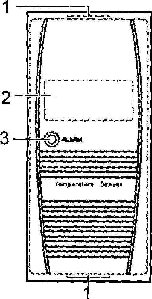
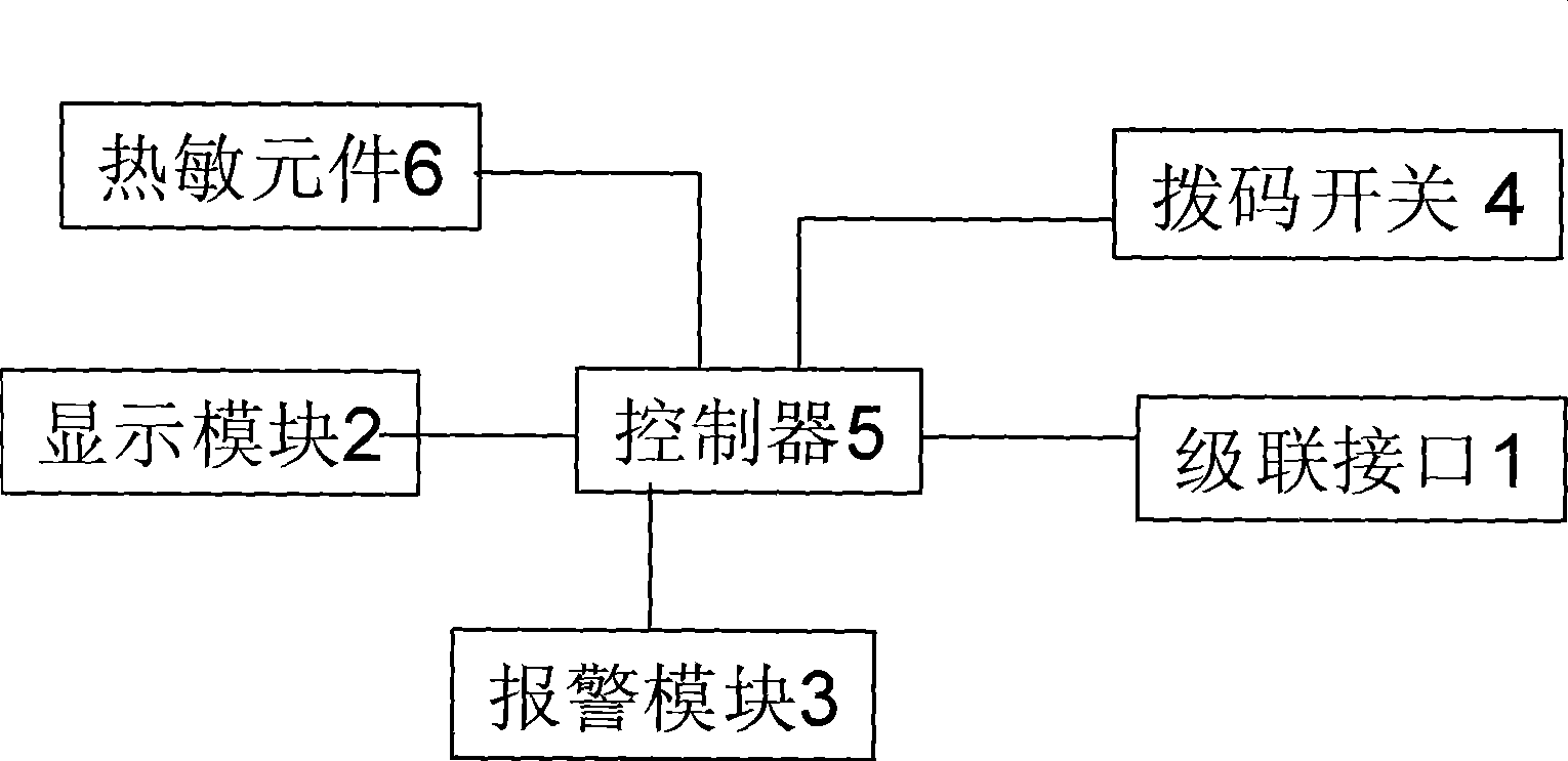
[0019] Such as figure 1 As shown, a temperature sensor includes a thermosensitive element 6 and a controller 5 . The thermosensitive element 6 is connected to the controller 5, and the thermosensitive element 6 outputs corresponding temperature signals to the controller 5 according to different temperatures in the machine room, and the controller 5 can obtain the temperature at the detection place after processing the temperature signal data. The thermal element 6 may be a thermal resistor, a thermal diode, a thermal reactor, or a thermal resonator.

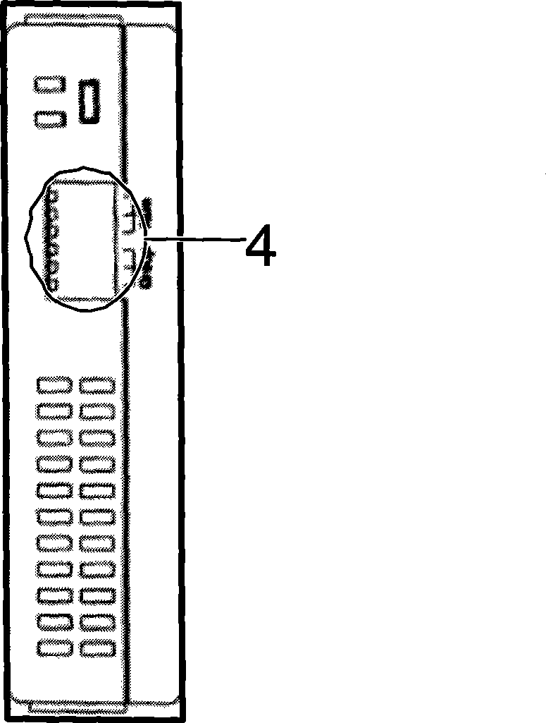
[0020] Such as figure 1 , 2 As shown in . The cascading interface 1 is used for electrical connection with other temperature sensors in the computer room or monitoring equipment in the computer room, and the dial switch 4 is used for setting the address of the temperature se...


PUM


Abstract

The invention discloses a temperature sensor. The temperature sensor comprises a thermosensitive element and a controller; the thermosensitive element is connected with the controller, and comprises a cascade interface and a dip switch; the cascade interface and the dip switch are respectively connected with the controller, the cascade interface is used for being electrically connected with other temperature sensors or monitoring equipment in a machine room, and the dip switch is used for setting the address of the temperature sensor. The temperature sensor is provided with the cascade interface and the dip switch, and can realize cascade connection of a plurality of the temperature sensors and then connection with the monitoring equipment, the various temperature sensors are distinguished from each other by the address set by the dip switch, and the control over a plurality of the temperature sensors can be achieved only by arranging an interface on the monitoring equipment, thus saving the cost.

Description

technical field [0001] The invention relates to a temperature sensor. Background technique [0002] The existing temperature sensors in the computer room detect a temperature and send it to the monitoring device through the interface. The monitoring equipment needs to detect the temperature of multiple locations in the equipment room. The monitoring equipment needs to be provided with many interfaces to be connected with different temperature sensors respectively, which makes the monitoring equipment have many interfaces and the cost is high. Contents of the invention [0003] The technical problem to be solved by the present invention is to propose a temperature sensor to reduce the cost of monitoring equipment in order to overcome the above deficiencies. [0004] Technical problem of the present invention is solved by following technical scheme: [0005] A temperature sensor, comprising a thermosensitive element and a controller, the thermosensitive element is connect...

Claims


Application Information

Patent Timeline
IPC IPC(8): G01K7/00G01K1/02
Inventor 毛福华曹发银吴凯薛波浪高谷
Owner EMERSON NETWORK POWER CO LTD
Learn More