High speed electric principal shaft system supported by five-freedom-degree AC magnetic bearing
A high-speed motorized spindle, high-speed spindle technology, applied in the directions of bearings, shafts and bearings, holding devices with magnetic attraction or thrust, etc., can solve the problems of high price of DC power amplifiers, limited application fields, and high cost, and achieve improved control. Accuracy and mechanical efficiency, high control accuracy, low cost effect
- Summary
- Abstract
- Description
- Claims
- Application Information
AI Technical Summary
Problems solved by technology
Method used
Image
Examples
Embodiment 1
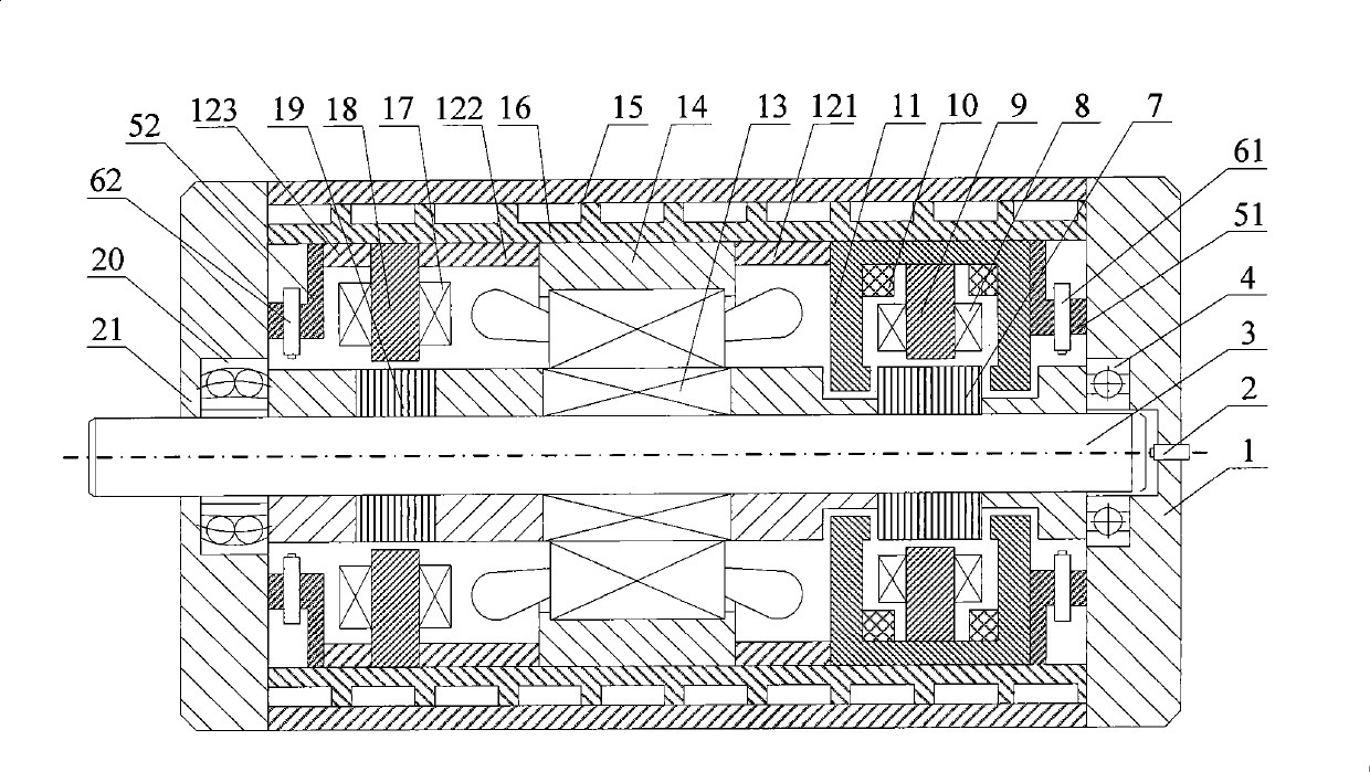
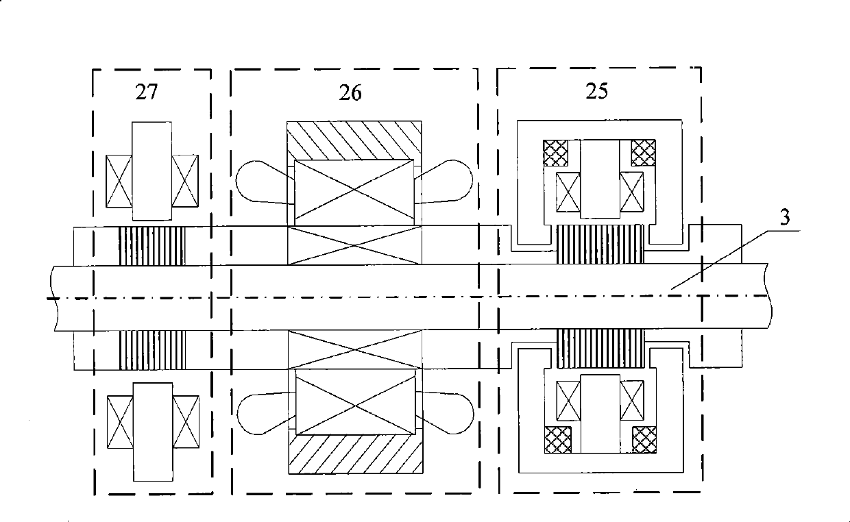
[0036] Such as figure 1 and figure 2 As shown, the high-speed motorized spindle system supported by a five-degree-of-freedom AC magnetic bearing, the mechanical structure is mainly composed of an AC-DC three-degree-of-freedom active magnetic bearing 25 pressed into a steel cylinder inner sleeve 16, a high-speed spindle motor 26, and an AC two-degree-of-freedom active The magnetic bearing 27 and the rotating shaft 3 constitute. figure 1 Among them, the axial displacement sensor probe 2 is installed on the right end cover 1, on the axis line of the rotating shaft 3, and detects the axial displacement of the rotating shaft 3; the radial auxiliary bearing 4 is fixed in the right end cover 1; 4 radial displacements at the right end The sensor probes 61 are evenly distributed along the circumference and fixed on the right end sensor bracket 51 between the right end cover 1 and the AC / DC three-degree-of-freedom active magnetic bearing 25 to detect the radial displacement of the rig...
Embodiment 2
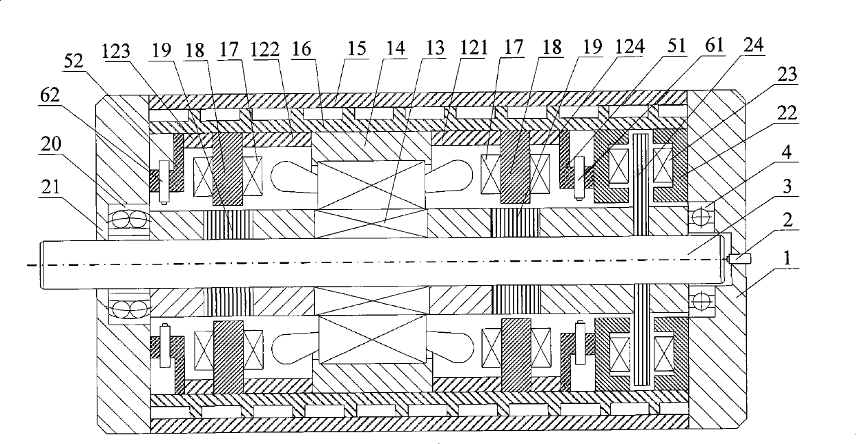
[0044] Such as image 3 and Figure 4 As shown, the high-speed motorized spindle system supported by a five-degree-of-freedom AC magnetic bearing, its mechanical structure is mainly composed of a high-speed spindle motor 26 press-fitted in a steel cylinder inner sleeve 16, two AC two-degree-of-freedom active magnetic bearings 27, an axial active The magnetic bearing 28 and the rotating shaft 3 constitute. image 3 Among them, the radial auxiliary bearing 4 and the radial-axial auxiliary bearing 20 are installed in the right end cover 1 and the left end cover 21 respectively; the axial displacement sensor probe 2 is installed on the right end cover 1 on the axis line of the rotating shaft 3, Detect the axial displacement of the rotating shaft 3; the axial DC active magnetic bearing 28 is installed close to the right end cover 1, the left side of which is the right end sensor bracket 51, and the four radial displacement sensor probes 61 at the right end are evenly distributed a...
PUM
 Abstract
Description
Claims
Application Information
 - R&D
- Intellectual Property
- Life Sciences
- Materials
- Tech Scout
- Unparalleled Data Quality
- Higher Quality Content
- 60% Fewer Hallucinations
Browse by: Latest US Patents, China's latest patents, Technical Efficacy Thesaurus, Application Domain, Technology Topic, Popular Technical Reports.
© 2025 PatSnap. All rights reserved.Legal|Privacy policy|Modern Slavery Act Transparency Statement|Sitemap|About US| Contact US: help@patsnap.com


