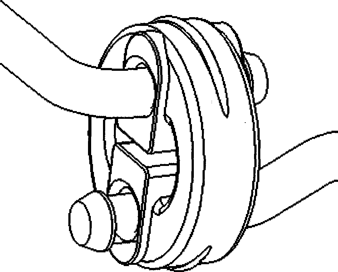
Novel exhaust system hanging mechanism
An exhaust system and hanging technology, which is applied in the direction of power unit gas intake, power unit, transportation and packaging, etc., can solve problems such as difficult to achieve vibration reduction effect, lack of limit structure, poor load-bearing capacity, etc., to achieve Improved vibration damping effect, simple mechanism structure, good vibration damping effect
- Summary
- Abstract
- Description
- Claims
- Application Information
AI Technical Summary
Problems solved by technology
Method used
Image
Examples
Embodiment 1
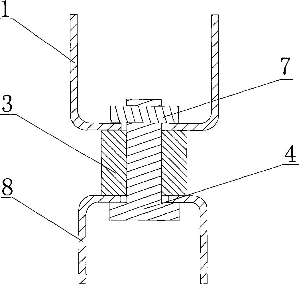
[0023] Such as figure 2 As shown, the exhaust system suspension mechanism of this embodiment includes an upper bracket 1 and a lower bracket 8, a main rubber block 3 is arranged between the upper bracket 1 and the lower bracket 8, and the upper bracket 1 and the lower bracket 8 pass through the upper bracket 8 in sequence. Bolts 4 and nuts 7 on the bottom surface of the bracket 1, the main rubber block 3 and the top surface of the lower bracket 8 are connected and fixed.
[0024] When installing and using, the upper bracket 1 is fixed on the vehicle frame or the vehicle body, the lower bracket 8 is connected to the exhaust system, the bolt 4 cooperates with the nut 7 to connect and fix the upper bracket 1 and the lower bracket 8, and the material of the bolt 4 is a rigid material, which can not only The exhaust system used to bear a large weight can also cooperate with the openings of the upper and lower brackets to prevent the horizontal displacement between the lower bracke...
Embodiment 2
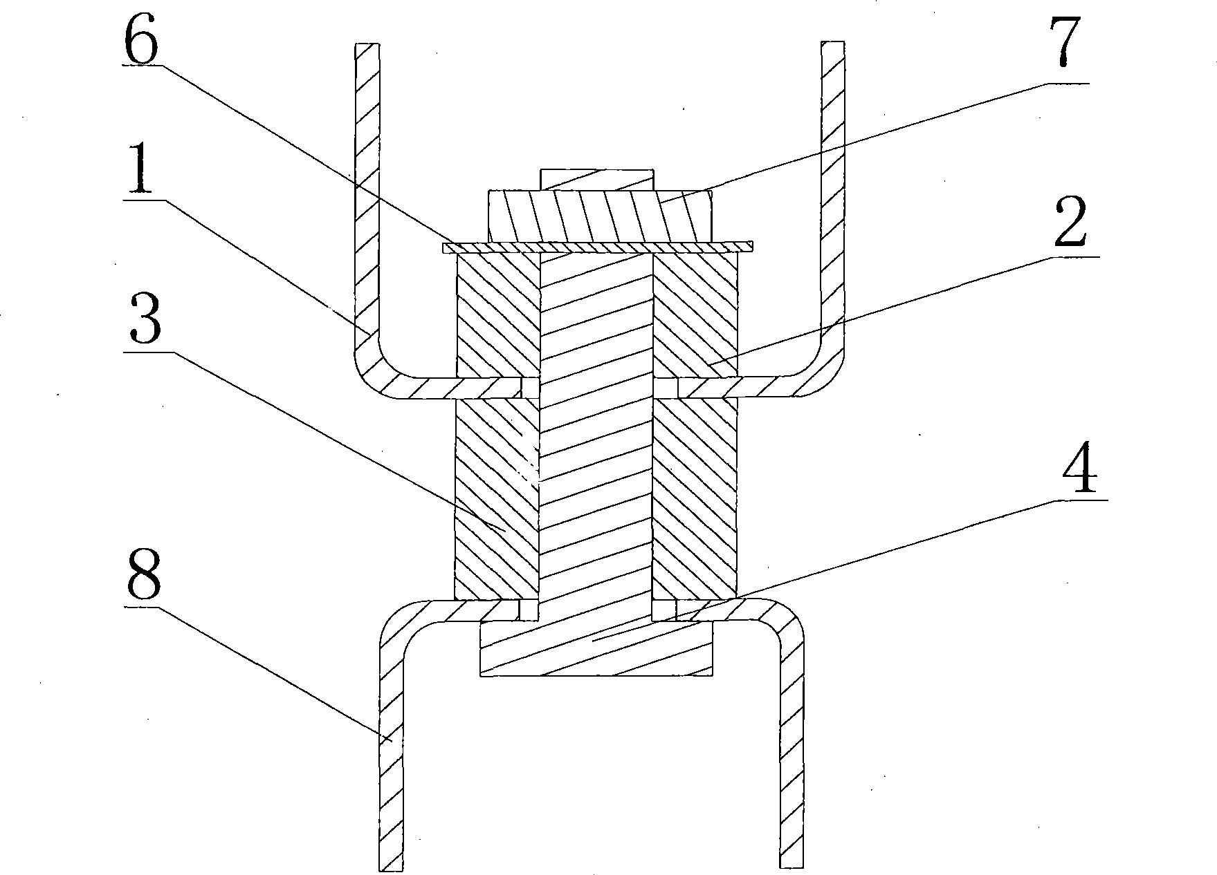
[0027] Such as image 3 As shown, the difference between this embodiment and Embodiment 1 is that an additional rubber block 2 and a gasket 6 are arranged above the bottom surface of the upper bracket 1 of this embodiment, and the bolt 4 passes through the gasket 6, the additional rubber block 2, The bottom surface of the upper bracket 1, the main rubber block 3 and the top surface of the lower bracket 8, and cooperate with the nut 7 to connect and fix the upper bracket 1 and the lower bracket 8. Under the action of the bolt 4 and the nut 7, the additional rubber block 2 is pressed by the gasket 6 and the bottom surface of the upper bracket 1 to produce a certain degree of elasticity, and the additional rubber block 2 cooperates with the main rubber block 3 to fix the bolt 4 and the The up and down displacement of the lower lower bracket 8 below plays a certain role of restriction and buffering, and improves the effect of vertical vibration reduction.
Embodiment 3
[0029] Such as Figure 4 As shown, different from the above-mentioned embodiments 1 and 2, this embodiment sets a sleeve 5 through the main rubber block 3, the bottom surface of the upper bracket 1, the additional rubber block 2 and the top surface of the lower bracket 8, and the bolts 4 pass through the pads in turn. Sheet 6, sleeve 5, and cooperate with nut 7 to connect and fix upper bracket 1 and lower bracket 8. There is a certain gap between the sleeve 5 and the bolt 4, so that the horizontal displacement of the bolt 4 and the lower bracket 8 fixed under the bolt 4 can be independent of the upper bracket 1, thereby reducing the impact on the upper body and improving the ride comfort .
[0030] The length of the sleeve 5 is slightly less than the sum of the height of the additional rubber block 2, the height of the main rubber block 3, the thickness of the bottom surface of the upper support 1, and the thickness of the top surface of the lower support 8. In this way, the...
PUM
 Abstract
Description
Claims
Application Information
 - R&D
- Intellectual Property
- Life Sciences
- Materials
- Tech Scout
- Unparalleled Data Quality
- Higher Quality Content
- 60% Fewer Hallucinations
Browse by: Latest US Patents, China's latest patents, Technical Efficacy Thesaurus, Application Domain, Technology Topic, Popular Technical Reports.
© 2025 PatSnap. All rights reserved.Legal|Privacy policy|Modern Slavery Act Transparency Statement|Sitemap|About US| Contact US: help@patsnap.com


