
Backlight module

A backlight module and backplane technology, applied in optics, nonlinear optics, lighting devices, etc., can solve the problems of reduced production capacity, complex rework, etc., and achieve the effects of reduced production costs, large contact area, and good commonality

Inactive Publication Date: 2010-09-15
AU OPTRONICS CORP
View PDF0 Cites 0 Cited by
  • Summary
  • Abstract
  • Description
  • Claims
  • Application Information

AI Technical Summary

Problems solved by technology

Even some lamp holders with different designs require special fixtures to disassemble and assemble, thus reducing production capacity and complicating rework

Method used


Image

  • Backlight module
  • Backlight module
  • Backlight module

Examples


Embodiment Construction

[0039] The technical features of the backlight module of the present invention will be described in detail below with reference to the accompanying drawings.

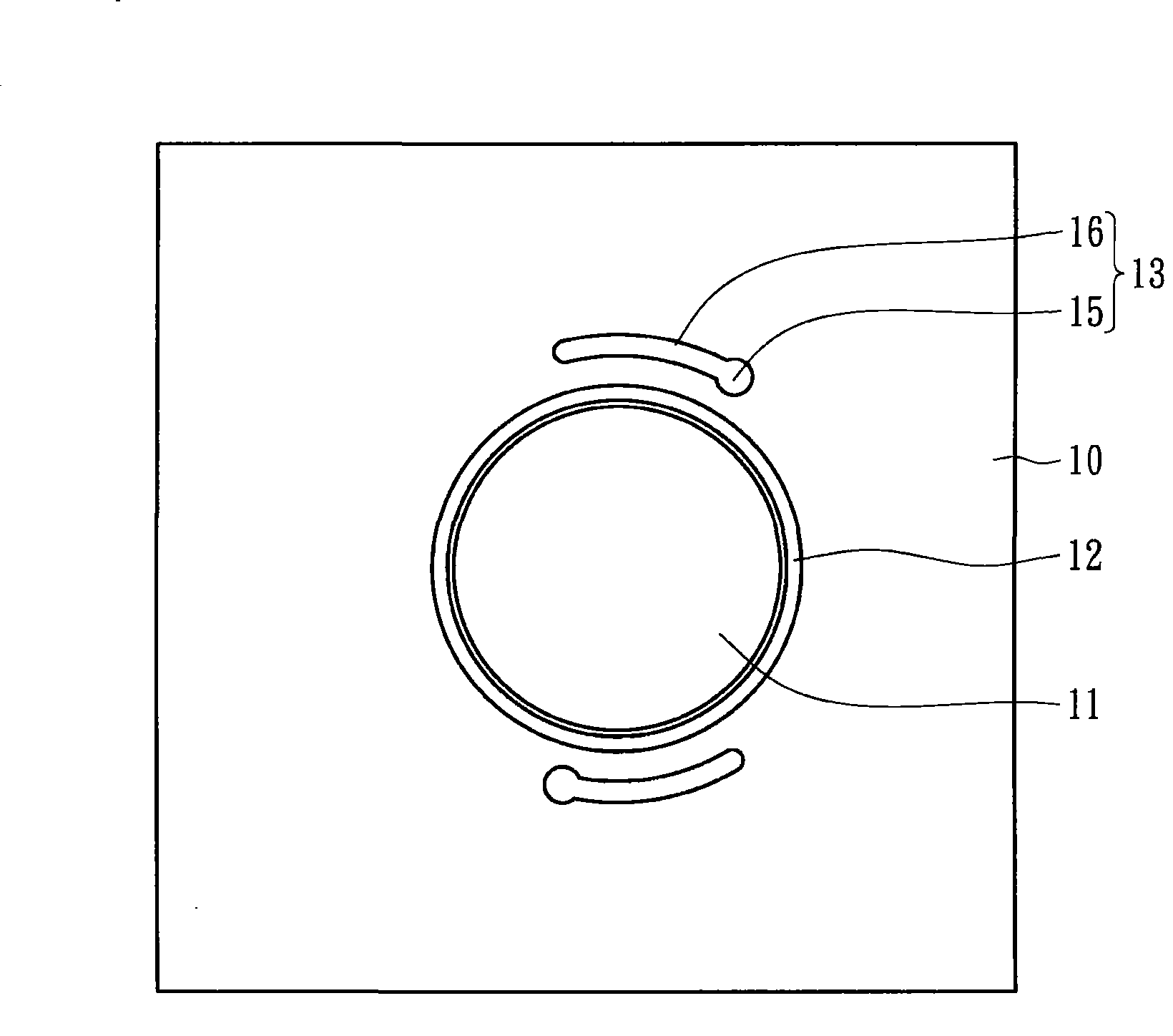
[0040] Figure 1A and 1B It is a top view and a side view of a backplane in a backlight module according to an embodiment of the present invention. The back plate 10 includes a hole 11 , and the hole 11 can be formed by stamping, so that a peripheral edge of the hole 11 protrudes downward to form an extension ring 12 . The two openings 13 are arranged corresponding to each other with respect to the hole 11 . In further words, each opening 13 includes an opening 15 and a slot 16 connected to the opening 15 , and the slot 16 extends along the circular arc periphery of the hole 11 .

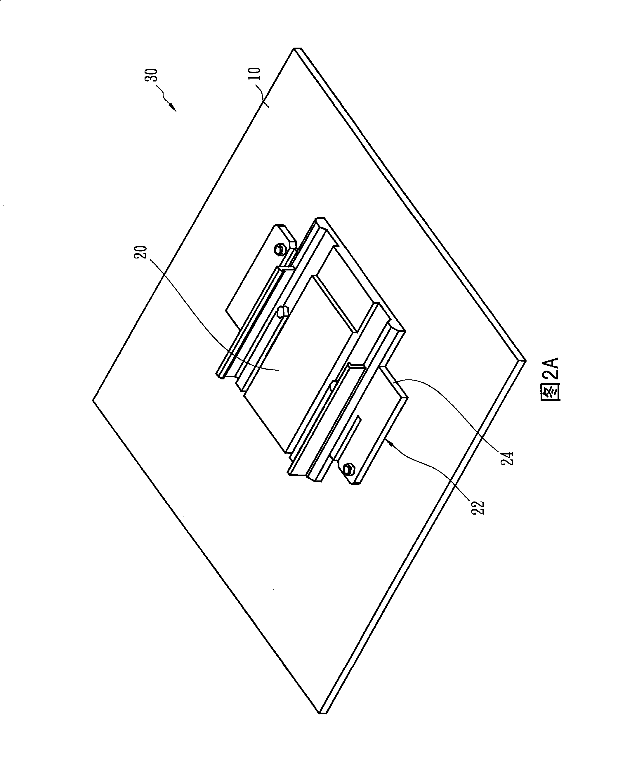
[0041] Figure 2A and 2B It is a three-dimensional schematic diagram of a backlight module including a lamp holder body and a backplane according to an embodiment of the present invention. Figure 2A and Figure 2B The top and bottom p...


PUM


Abstract

The invention relates to a backlight module, which comprises a backboard and a lamp holder body. The backboard is provided with a hole. The lamp holder body is provided with a positioning part and a clamping part, wherein the positioning part is positioned at the lower section of the lamp holder body, comprises a flank of thread and is matched with the hole. The clamping part is arranged at the lateral margin of the lamp holder body, is positioned above the positioning part and is embedded on the backboard. The backlight module can also comprise an elastic sheet additionally. Thus, the problem that a hook is easily damaged in collision can be avoided. Moreover, compared with the design of the hook of the prior lamp holder, the backlight module has larger contact area, and can prevent the noise generated due to collision and shake. In addition, the backlight module can use backboards with various thicknesses, has good commonness, thereby reducing the production cost.

Description

technical field [0001] The invention relates to a backlight module, wherein the backlight module includes a lamp socket body and a back plate. Background technique [0002] A backlight unit (Back light unit) is one of key components of a liquid crystal display (Liquid Crystal Display, LCD). Since the liquid crystal itself does not emit light, the function of the backlight module is to supply sufficient brightness and evenly distributed light source so that it can display images normally. Liquid crystal displays are now widely used in electronic products with growth potential such as monitors, notebook computers, digital cameras and projectors, thus driving the demand for backlight modules and related components to continue to grow. [0003] The light tubes in the traditional backlight module are fixed on the back bezel by using the lamp holder structure. Corresponding hooks are formed at the junction of the lamp holder structure and the backboard to hold the lamp holder st...

Claims


Application Information

Patent Timeline
Patent Type & Authority Patents(China)
IPC IPC(8): G02F1/13357F21V21/00
Inventor 李彦霖田謦辅傅世泽魏肇治
Owner AU OPTRONICS CORP
Learn More