
Voltage stabilizing method and device for single phase DC-to-AC converter

A technology of single-phase inverter and voltage stabilization control, which is applied in control/regulation systems, instruments, and irreversible DC power input to AC power output, etc. The effect and other issues, to achieve the effect of high voltage regulation accuracy and fast dynamic response speed

Active Publication Date: 2009-04-29
SHENZHEN KSTAR SCI & TECH
View PDF0 Cites 5 Cited by
  • Summary
  • Abstract
  • Description
  • Claims
  • Application Information

AI Technical Summary

Problems solved by technology

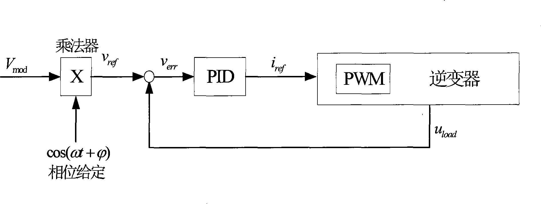
[0004] The disadvantage of existing single-phase inverters is that the instantaneous value of the voltage is given by v ref From constant flow voltage modulo given V mod and AC sine wave cos(ωt+ ) product
However, the disadvantage of this method is that if the effective value is obtained through a hardware circuit, a large filter must be added. If it is calculated by software, the general method can only calculate the effective value once every interval of a power frequency cycle, that is, It is said that the effective value can be adjusted once every interval of a power frequency cycle, so that the adjustment cycle of the effective value adjustment will be longer, and the response to similar load changes such as sudden increase and sudden unloading will be slower
This will affect the dynamic response speed of the voltage control loop, voltage regulation speed, etc.
Even if the effective value is calculated in real time by software (which will take up more storage resources and code execution time), the calculated effective value can only reflect the magnitude of the voltage in one cycle before each calculation time, and for a certain time load The sudden change in voltage caused by the sudden change, due to the periodicity of the effective value calculation, the sudden change in voltage will be integrated by the stable voltage at other times in the whole cycle, and it is difficult to show the real-time change of the voltage, thus affecting the adjustment effect
The hardware method generally adopts the method of rectifying and filtering the AC voltage after sampling to obtain the feedback value that is actually the average value of the voltage, and then adjusts the voltage. Since a low-pass filter with a large time constant is required, the lag time will be longer
In summary, the use of effective value for non-difference adjustment determines that the adjustment has relatively poor real-time performance, and the adjustment delay is relatively large, which affects the dynamic response of the adjustment and leads to poor dynamic performance of the inverter.

Method used


Image

  • Voltage stabilizing method and device for single phase DC-to-AC converter
  • Voltage stabilizing method and device for single phase DC-to-AC converter
  • Voltage stabilizing method and device for single phase DC-to-AC converter

Examples


specific Embodiment approach 1

[0031] Such as image 3 As shown, a single-phase inverter voltage stabilization control method includes the following steps:

[0032] Step 1: Obtain the actual output voltage modulus of the single-phase inverter. The specific operation is as follows: collect the instantaneous value u of the output voltage of the single-phase inverter, obtain the output voltage change rate u′ of the single-phase inverter, according to V act = u 2 + ( u ′ ω ) 2 Get the actual output voltage modulus of the single-phase inverter, where V act is the actual output voltage modulus of the single-phase inverter, u is the instantaneous value of the output voltage of the single-phase inverter, u' is the rate of c...

specific Embodiment approach 2

[0047] Such as Figure 6 As shown, the difference between this specific embodiment and the first specific embodiment is that the voltage instantaneous value adjustment is added. This embodiment also includes the following steps:

[0048] Step 4: Obtain the instantaneous value of the given voltage of the single-phase inverter. The multiplier moduloes the voltage to a given V mod The cosine value cos(ωt+ ) multiplied to obtain the instantaneous value of the given voltage v ref .

[0049] Step 5: Obtain an error of the instantaneous voltage according to the instantaneous value of the output voltage of the single-phase inverter and the instantaneous value of the given voltage. Use a subtractor to convert the instantaneous value of the given voltage v ref Subtract the actual instantaneous voltage u to get the error v of the instantaneous voltage err2 .

[0050] Step 6: According to the error of the instantaneous voltage v err2 is adjusted to obtain a second adjustment amo...


PUM


Abstract

The invention discloses a single-phase inverter stabilizer control method and a device thereof; wherein, the method comprises the steps as follows: the practical output voltage modulus of the inverter is gained; the error of the practical voltage modulus is gained according to the given output voltage modulus and the practical output voltage modulus; the error is adjusted by integral and by multiplying a cosine value with the given phase so as to gain a first adjusting quantity; according to the first adjusting quantity, the output voltage of the inverter is adjusted; the device comprises a practical output voltage modulus gaining unit, a subtracter, an adjuster and a multiplier; the practical output voltage modulus gaining unit gains the practical voltage modulus and outputs the practical voltage modulus to the subtracter, which gains the error according to the given voltage modulus and the practical voltage modulus and outputs the error to the adjuster, which carries out integral adjustment on the error and outputs the value to the multiplier, which multiplies the value output by the adjuster with the cosine value with the given phase so as to gain the first adjusting quantity and outputs the first adjusting quantity to the inverter. The invention has the advantages of high stabilizer precision and quick dynamic response speed.

Description

technical field [0001] The invention relates to a single-phase inverter voltage stabilization control method, and the invention also relates to a single-phase inverter voltage stabilization control device. Background technique [0002] For a three-phase inverter whose output AC voltage differs by 120 degrees, vector control is usually used to convert the three-phase voltage into a vector with a fixed vector length and rotate at a certain speed for control and adjustment. That is, the three-phase A / B / C voltage is transformed into the d / q / 0 coordinate system through coordinate transformation, so that the given three-phase AC voltage becomes the given d / q / 0 three DCs. Under d / q / 0 coordinates, three DC given errors can be adjusted. Since the DC given error is adjusted, the static error can be eliminated in theory, so that the voltage regulation accuracy control of the output voltage of the three-phase inverter becomes relatively easy. But for single-phase inverters, the above-...

Claims


Application Information

Patent Timeline
IPC IPC(8): H02M7/44G05F1/44
Inventor 陈佳杨戈戈刘程宇
Owner SHENZHEN KSTAR SCI & TECH
Learn More