Method and circuit used for parallel IGBT dynamic flow equalization

A parallel and dynamic technology, applied in circuits, electronic switches, electrical components, etc., can solve the problems of difficulty in implementation and narrow adjustment range, and achieve the effect of good current sharing effect, high reliability and simple implementation.

Inactive Publication Date: 2009-04-29
BYD CO LTD
View PDF0 Cites 21 Cited by
  • Summary
  • Abstract
  • Description
  • Claims
  • Application Information

AI Technical Summary

Problems solved by technology

[0004] The present invention aims at the disadvantages of difficulty in realization and narrow adjustment range of the scheme of changing grid resistance to achieve current sharing in the prior art, and provides a method and circuit for dynamic current sharing of parallel IGBTs. The method and circuit have the advantages of simple implementation, adjustable Good effect

Method used


Image

  • Method and circuit used for parallel IGBT dynamic flow equalization
  • Method and circuit used for parallel IGBT dynamic flow equalization
  • Method and circuit used for parallel IGBT dynamic flow equalization

Examples


Embodiment Construction

[0012] The present invention will be further described below in conjunction with the accompanying drawings.

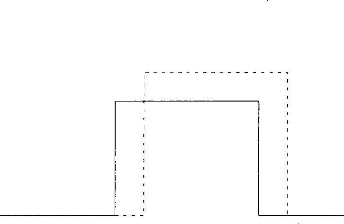
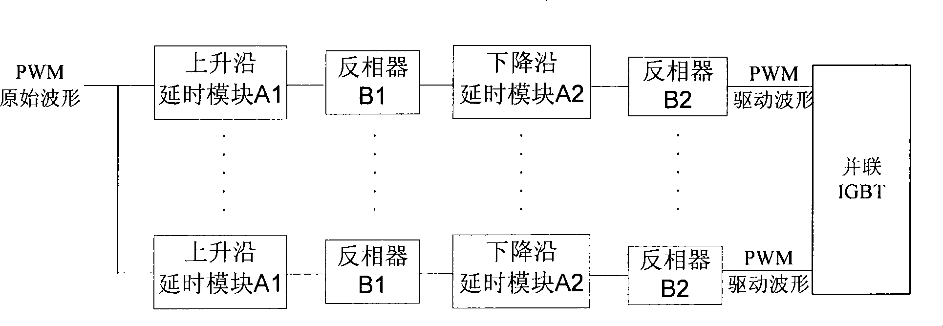
[0013] The present invention provides a method for dynamic current sharing of parallel IGBTs, wherein the method includes the following steps: delaying the original PWM waveform to obtain an asynchronous PWM driving waveform; and using the obtained asynchronous PWM driving waveform To drive parallel IGBTs, so that the output waveforms of the driven parallel IGBTs of each IGBT are synchronized.

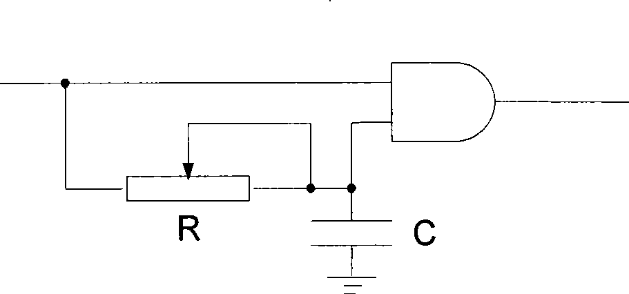
[0014] Wherein, delaying the PWM original waveform includes the following steps: input the PWM original waveform into multiple delay circuits; each delay circuit delays the rising and falling edges of the input PWM original waveform. here, as figure 2 As shown, the steps for the delay circuit to delay the rising and falling edges of the original PWM waveform include: the delay circuit first delays the rising edge of the input PWM original waveform by using the rising edge del...


PUM


Abstract

The present invention provides a method and a circuit for dynamic flow equalization of parallel IGBTs. The method comprises the following steps that a time delay is performed to a PWM original waveform to obtain asynchronous PWM drive waveforms; the obtained asynchronous PWM drive waveforms are used to drive the parallel IGBTs to realize that the output waveforms of each IGBT are synchronous. The present invention provides a method and a circuit for dynamic flow equalization of parallel IGBTs. The circuit comprises multiple time-delay circuits each of which is used for performing time delay to PMW original waveforms to obtain asynchronous PWM drive waveforms to make that output waveforms of all the driven parallel IGBTs are synchronous. According to the present invention, comparing with a grid resistance compensating method of the prior art, the method of using time delay to obtain asynchronous PWM drive waveforms to drive parallel IGBTs to form that the output waveforms of all the parallel IGBTs are synchronous, has the characteristics of simple realization, high reliability and good modulation effect.

Description

technical field [0001] The invention relates to a method and a circuit for dynamic current sharing of parallel insulated gate bipolar transistors (IGBT). Background technique [0002] Parallel operation of insulated gate bipolar transistors (IGBTs) can withstand higher load currents, but at the same time due to the threshold voltage U of each IGBT in parallel GE , Miller capacitance C GE , Emitter inductance L G , gate resistance R G , Gate lead inductance L G , Gate capacitance C GE The difference between the turn-on and turn-off times of each device in the parallel IGBT is inconsistent, which leads to the problem of dynamic uneven current, such as figure 1 As shown, the solid line represents the gate-emitter voltage waveform of one of the parallel IGBTs, which is first turned on and then turned off, and the dotted line represents the gate voltage waveform of the other parallel IGBT, which is turned on and then turned off The dynamic uneven current will cause the IGBT...

Claims


Application Information

Patent Timeline
IPC IPC(8): H03K17/08H03K17/60
Inventor 彭应葱
Owner BYD CO LTD
Why Eureka
Try Eureka